Method and Device For Determining the State of Degradation of a Lubricant Oil

a technology of hydraulic oil and degradation state, which is applied in the direction of measuring devices, scientific instruments, instruments, etc., can solve the problems affecting the efficiency of equipment, etc., so as to achieve the effect of reducing the useful life of equipment even wors

Active Publication Date: 2014-05-29
ATTEN2 ADVANCED MONITORING TECH S L U
View PDF0 Cites 10 Cited by
  • Summary
  • Abstract
  • Description
  • Claims
  • Application Information

AI Technical Summary

Benefits of technology

[0014]d. obtaining the total degradation value as OD(%)=100−100*LOG10 (CIREF / CI). The corresponding device comprises a strong white light, a fluidic cell adapted for the passage of oil through it, a detector capable of transforming the amount of light emitted by the source and absorbed by the oil into an electric signal of the transmittance in the visible and programming means to carry out the aforementioned process. Optionally, it also comprises a particle filter and means for eliminating bubbles in oil.

Problems solved by technology

Industrial machinery, either energy generating motors or compressors, multipliers, etc. undergoes a lot of stops and failures due to degradation of lubricant and hydraulic oils.
This issue causes risky situations when these machines are used as a component of more complex systems, so that the consequence of a stop in these cases is even worst, both from a point of view of cost and machine safety.
The reduction in useful lifetime of the equipment frequently causes unnecessary maintenance costs and current “off-line” measurement methodologies do not provide an early enough detection of the degradation process.
. . ) this control methodology implies a significant logistic and economic burden for a very small environment.
These methods have the limitation of only contemplating the oxidative degradation of oil, even though AN is one of the most indicative parameters of the lubricant oil state.
Besides, this equipment cannot be used in motors due to the carbon generated during the combustion process.
The method, however, does not allow knowing the remaining life of oil.
The use of a single band causes not having a high sensitivity and the result being affected by other factors.

Method used


Image

  • Method and Device For Determining the State of Degradation of a Lubricant Oil
  • Method and Device For Determining the State of Degradation of a Lubricant Oil
  • Method and Device For Determining the State of Degradation of a Lubricant Oil

Examples


Embodiment Construction

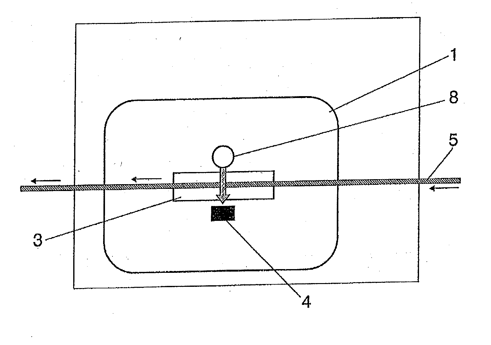
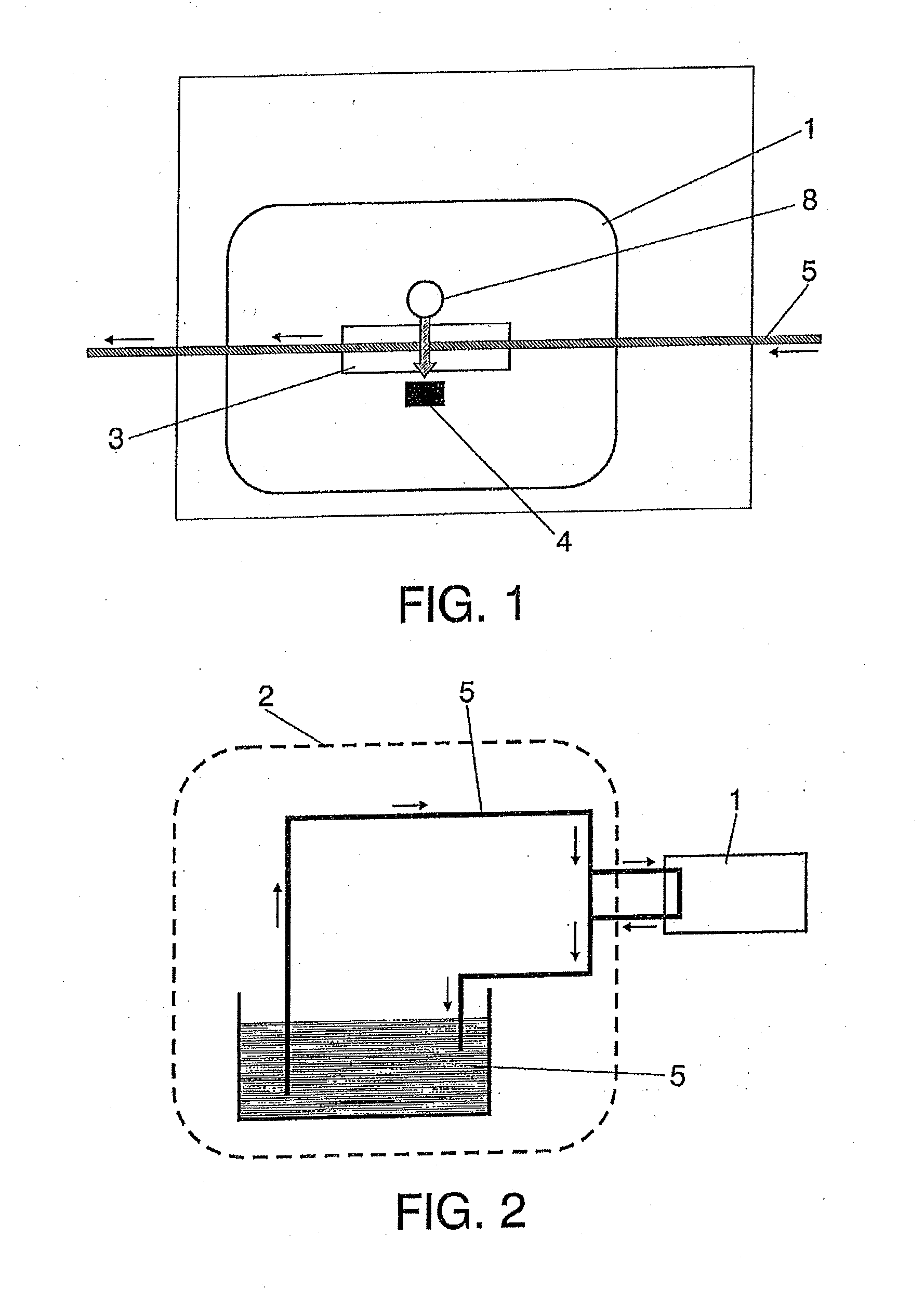
[0019]Referring to FIGS. 1 and 2, the sensor of the invention (1) is devised to be installed in a by-pass of the lubrication system (2). The system takes advantage of the difference in pressure needed for the oil (5) to circulate through the sensor. The oil, after by-pass, goes through a series of hydraulic components inside the sensor: an electrovalve that manages the passage of oil through the device, a particle filter to eliminate particles of a certain size, and a system to eliminate bubbles that are generated in the oil's circulation system. After going through all the hydraulic elements, the oil goes to the fluidic cell (3) where the measurement will take place. This cell has an established light passage. With the oil already inside the cell, a white light beam is placed on the visible range of the spectrum through a LED-type emitter (8) and the light that is not absorbed by the oil is collected by a detector (i.e. a photodiode). The detector (4) collects the light in several ...


PUM

PropertyMeasurementUnit
transmittanceaaaaaaaaaa
color indexesaaaaaaaaaa
color indexaaaaaaaaaa

Abstract

The present invention provides a method and a device for determining the degradation of a used oil. The method of the invention is based on calculating the components in the red, green and blue transmission spectral bands IR0, IG0 and IB0 of the unused oil, carrying out a number of measurements of the transmittance of the same oil after use, calculating the colour indices of the used oil and the reference colour index as CI=1×IR+0.5×I0+0.5IBCIREF=1×IR00.5×IG0+0.5IB0 and obtaining the overall degradation value as OD(%)=100−100×log10 (CIREF / CI). By virtue of the method and the corresponding device, real-time monitoring of oil degradation is facilitated.

Description

FIELD OF THE INVENTION[0001]The present invention relates to a method to determine the state of degradation of lubricant and hydraulic oil. More precisely, it relates to a method and device to provide an accurate reading of the total degradation throughout the use of oil by measuring the transmittance in the visible range of the color spectrum of said oil.BACKGROUND OF THE INVENTION[0002]The need for using appropriate sensors to carry out industrial oil monitoring has been acknowledge as a critical area by operating engineers, machinery manufacturers and even standard regulation organizations, especially during the last years, wherein the reliability, efficiency and safety on processes and / or products plays a very important role.[0003]Industrial machinery, either energy generating motors or compressors, multipliers, etc. undergoes a lot of stops and failures due to degradation of lubricant and hydraulic oils. This issue causes risky situations when these machines are used as a compo...

Claims


Application Information

Patent Timeline
Patent Type & Authority Applications(United States)
IPC IPC(8): G01N21/31
CPCG01N21/31G01N21/25G01N33/2888
Inventor ARRONDO, ENEKO GORRITXATEGIIRIGARAY, AITOR ARNAIZGARCIA, ANA ARANZABEAZQUETA, JES S MA TERRADILLOS
Owner ATTEN2 ADVANCED MONITORING TECH S L U
Why Eureka
Try Eureka