Pulsed power generator

a generator and pulse technology, applied in the field of pulse power generators, can solve the problems of short apparatus life, inability to control pulse width, and inability to use dc high voltage power sources, etc., to achieve the effect of simple circuit configuration, reduced voltage droop, and increased cost and volum

Active Publication Date: 2014-05-29
KOREA ELECTROTECH RES INST
View PDF0 Cites 51 Cited by
  • Summary
  • Abstract
  • Description
  • Claims
  • Application Information

AI Technical Summary

Benefits of technology

[0032]The present invention relates to a pulse power generator which can minimize a voltage droop generated during the application

Problems solved by technology

A typical high voltage pulse generating circuit has many limitations in terms of the lifespan of the apparatus, the variation of the pulse width, the increase of the pulse repetition rate, the control of the pulse voltage, and the necessity of the DC high voltage power source.
However, these methods have limitations in that the lifespan of the apparatus is short and the pulse width is impossible to control.
Also, there are limitations in that it is difficult to increase the pulse repetition rate and a DC high voltage power supply circuit is needed.
Also, since a method of using a pulse transformer is difficult to obtain a rapid rise time of a pulse due to the leakage inductance of the transformer, and a reset circuit needs to be added due to the self-saturation of the transformer, the circuit becomes complex, noise occurs and the pulse width is difficult to extend.
However, the IGBT also has operational limitations such as switching driving and uniform voltage distribution, causing the limitations of the product reliability.
In this case, when IGBTs turn on/off, a voltage unbalance may be easily generated due to a difference of the driving timing, and thus may immediately damage the IGBTs when overpassing the voltag

Method used


Image

  • Pulsed power generator
  • Pulsed power generator
  • Pulsed power generator

Examples


Embodiment Construction

[0049]Hereinafter reference will now be made in detail to various embodiments of the present invention, examples of which are illustrated in the accompanying drawings and described below. While the invention will be described in conjunction with exemplary embodiments, it will be understood that present description is not intended to limit the invention to those exemplary embodiments. On the contrary, the invention is intended to cover not only the exemplary embodiments, but also various alternatives, modifications, equivalents and other embodiments, which may be included within the spirit and scope of the invention as defined by the appended claims.

[0050]The above and other features of the invention are discussed infra.

[0051]Hereinafter, exemplary embodiments of the present invention will be described in detail with reference to the accompanying drawings so that those skilled in the art can easily carry out the present invention.

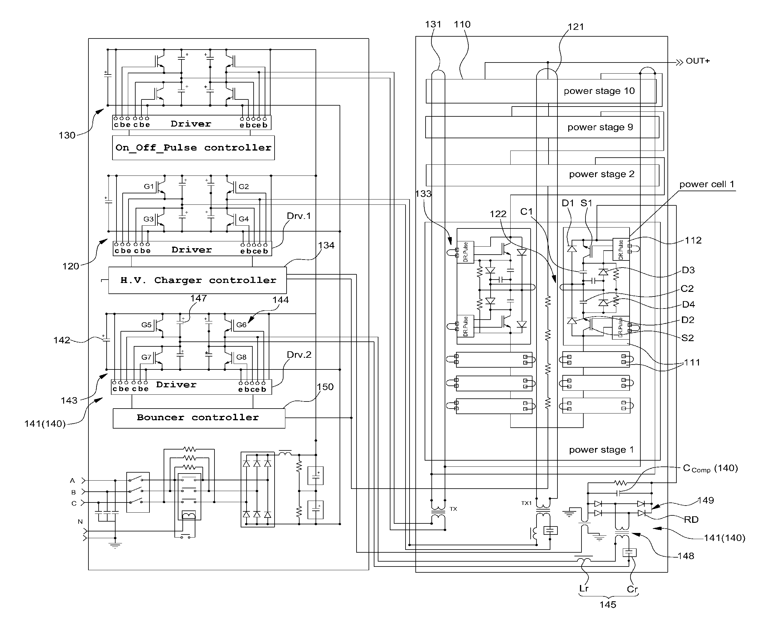
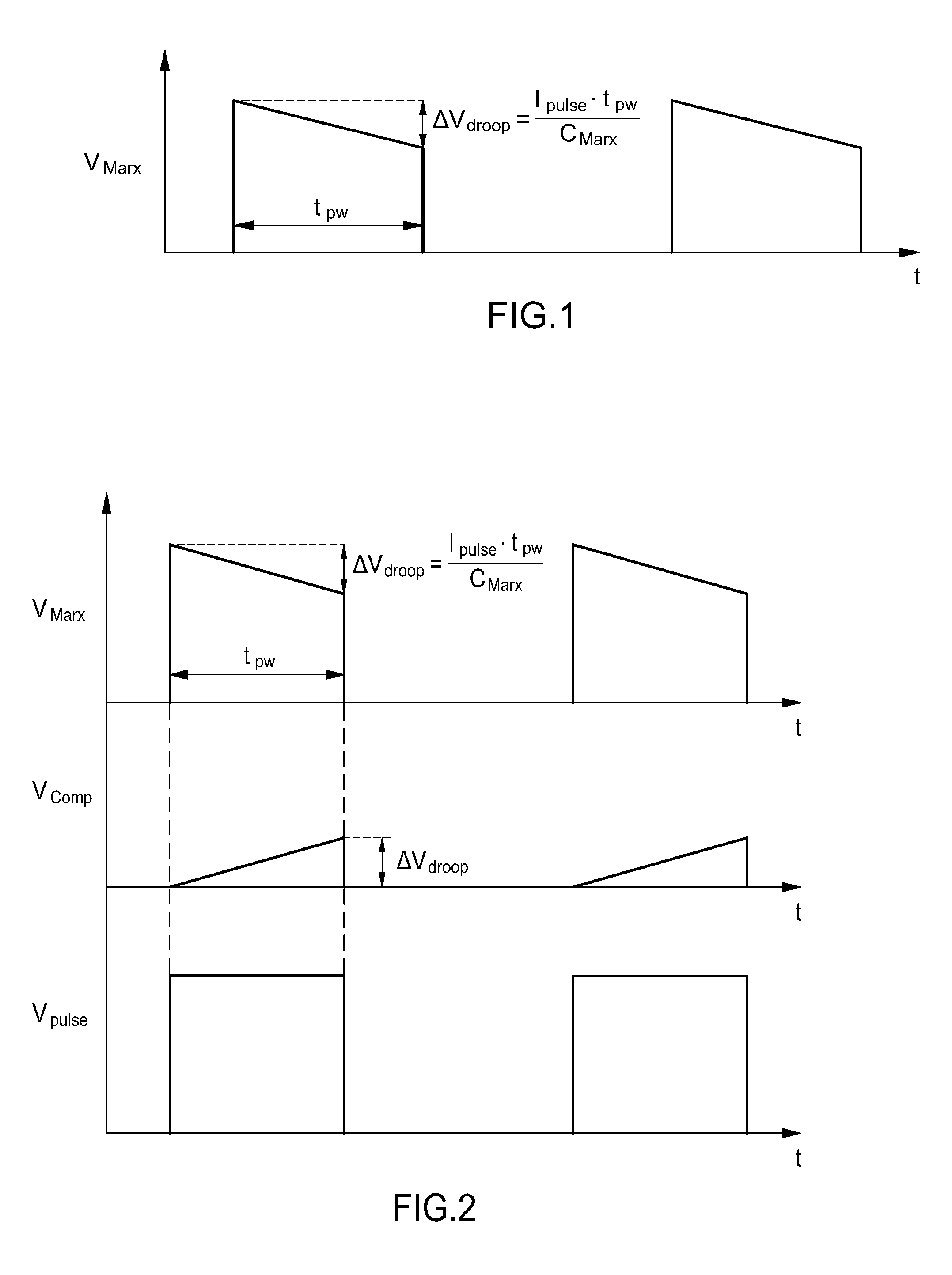
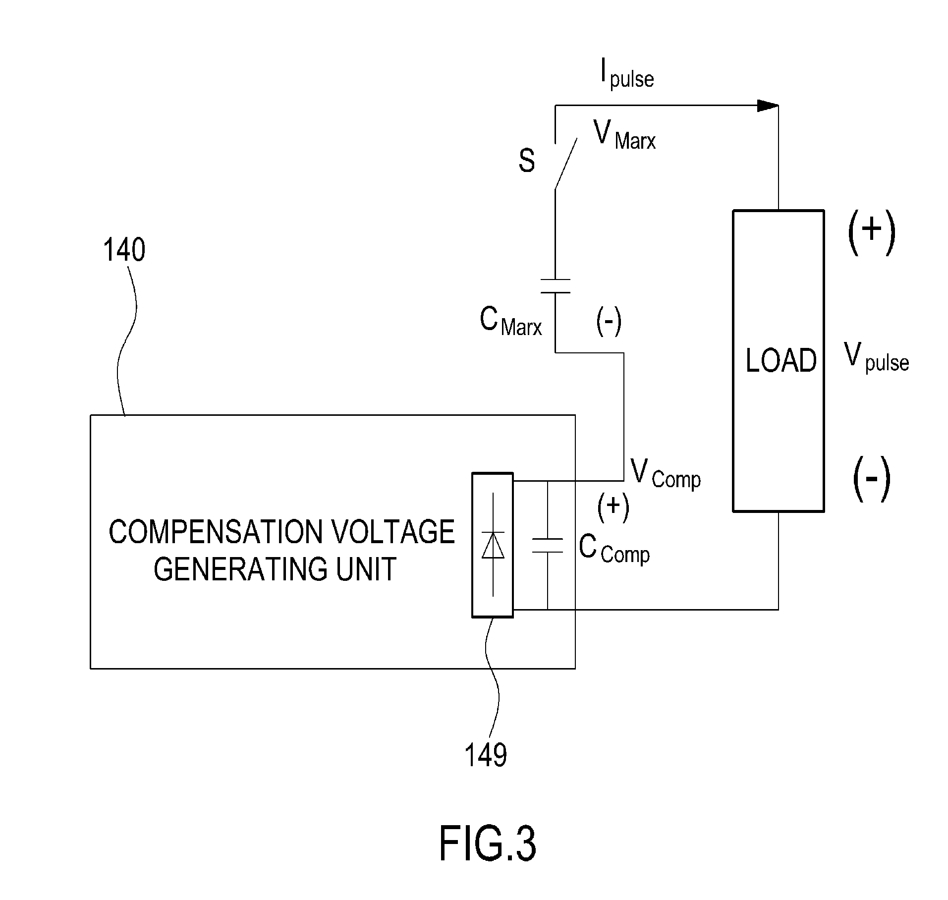
[0052]The present invention relates to an active volta...


PUM


Abstract

An active voltage drop control-type pulse power generator includes power stages, a power inverter, a power loop, a control inverter, a control loop, and a compensation unit. The power stages include power cells connected in series. Each power cell includes a switch and a capacitor connected in series, a driver for driving the switch, a bypass diode connected to both ends of the switch, and a rectifying diode connected to both ends of the capacitor. The power inverter charges the capacitor via the power loop and the rectifying diode inside each power cell. The control inverter provides a control signal for the switch via the control loop and the driver inside each power cell. The compensation unit is connected to one of the power cells and generates a compensation voltage for compensating for a voltage drop at a load according to a voltage detected in real-time from the power cell.

Description

CROSS-REFERENCE TO RELATED APPLICATION[0001]This application claims under 35 U.S.C. §119(a) the benefit of Korean Patent Application No. 10-2012-0134291 filed Nov. 26, 2012, the entire contents of which are incorporated herein by reference.BACKGROUND[0002](a) Technical Field[0003]The present invention relates to a pulse power generator. More particularly, the present invention relates to a pulse power generator which can minimize a voltage droop generated during the application of a high voltage pulse by additionally including a simple circuit configuration without a significant increase in cost and volume.[0004](b) Background Art[0005]Generally, a high voltage pulse generating circuit uses apparatuses such as a plasma generator (PSII etc.) or various kinds of test equipment, which require a high voltage as a load. A typical high voltage pulse generating circuit has many limitations in terms of the lifespan of the apparatus, the variation of the pulse width, the increase of the puls...

Claims


Application Information

Patent Timeline
IPC IPC(8): H02M3/335
CPCH02M3/335H02M3/28H02M7/10H03K3/53
Inventor RYOO, HONG JEJANG, SUNG ROCRIM, GEUN HIEKIM, JONG SOO
Owner KOREA ELECTROTECH RES INST
Why Eureka
Try Eureka