
Method of grouping stations in multi-transmission

Inactive Publication Date: 2014-05-29
ELECTRONICS & TELECOMM RES INST
View PDF6 Cites 22 Cited by
  • Summary
  • Abstract
  • Description
  • Claims
  • Application Information

AI Technical Summary

Benefits of technology

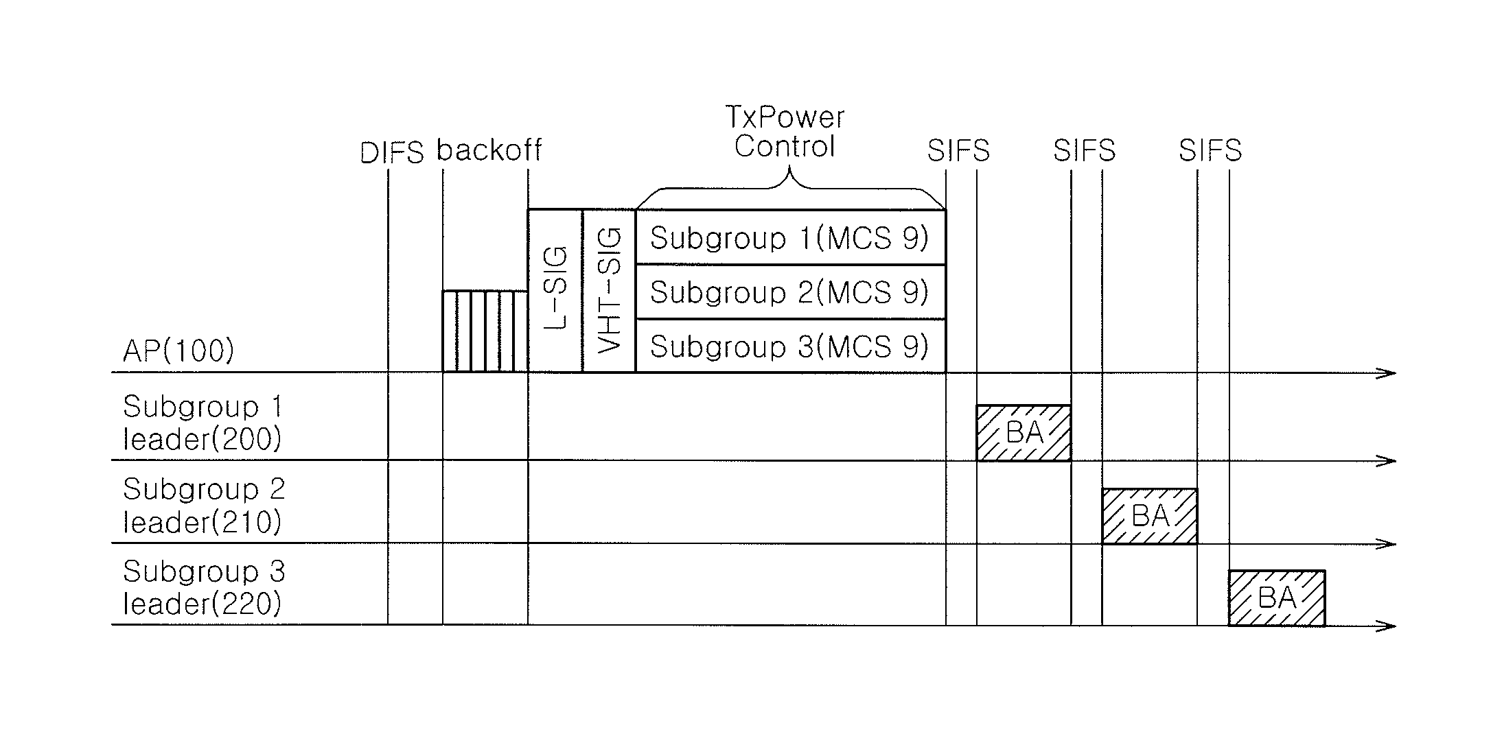
The present invention provides an apparatus and method for efficient multicasting in a multi-transmission environment. By grouping multicast receivers based on channel quality and using proper transmission power control and modulation coding scheme for each subgroup, the invention increases efficiency of down-link frame multicasting and provides high fairness between multicast receivers.

Problems solved by technology

However, the multicast technology suffers from many obstacles in a WLAN environment.
In this situation, even a single frame error may cause a loss of data.
These are not suitable for applications that require QoS such as a voice over IP (VoIP), video conferencing, IP television (IPTV), etc.
Even though this can be suitable for noisy channels in case of high SNR channel transmission with low data rate causes significant inefficiency.
It can also negatively affect other multicast or unicast data streams since they have to wait longer for the channel access.
The multicasting provides an unreliable delivery in many other WLAN technologies such as HiperLAN or HipreLAN / 2, and AlohaNet.
The A-MSDU has an overhead lower than the A-MPDU aggregation, but is less efficient in a noisy channel environment.
However, these solutions have also problems in terms of scalability and efficiency.

Method used


Image

  • Method of grouping stations in multi-transmission
  • Method of grouping stations in multi-transmission
  • Method of grouping stations in multi-transmission

Examples


Embodiment Construction

[0032]Hereinafter, the embodiments of the present invention will be described in detail with reference to the accompanying drawings. In the following description, well-known functions or constitutions will not be described in detail if they would unnecessarily obscure the embodiments of the invention. Further, the terminologies to be described below are defined in consideration of functions in the invention and may vary depending on a user's or operator's intention or practice. Accordingly, the definition may be made on a basis of the content throughout the specification.

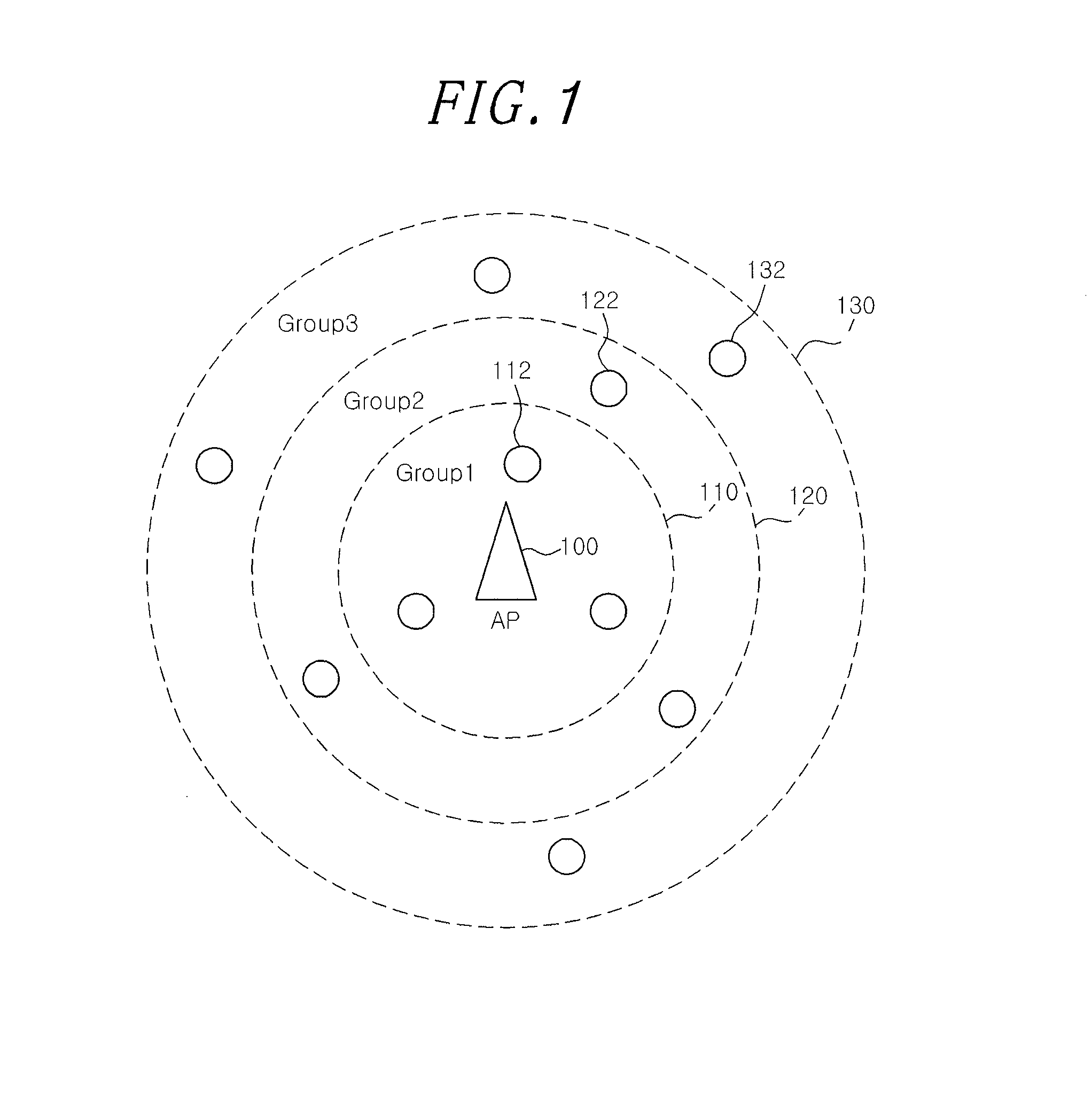
[0033]In an actual WLAN scenario of an example, all of the stations within one cell are non-uniformly distributed around an AP (Access Point). In this situation, some of the stations are located far away from the AP and hence has a low SNR value. On the other hand, some of the stations are located very closely to the AP and hence has excellent signal strength. As well known in the art, a signal level that is receive...


PUM


Abstract

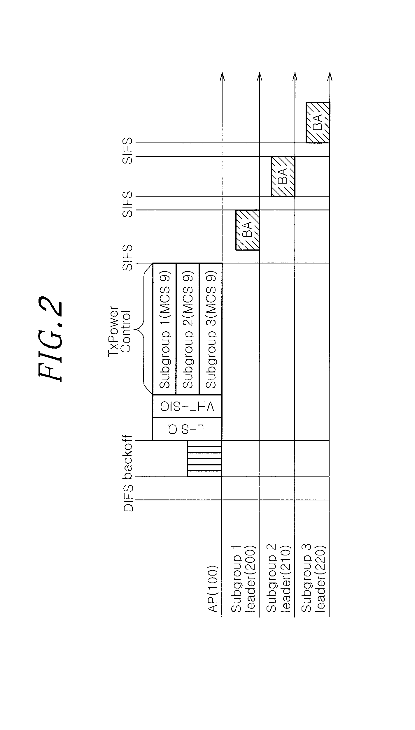
An apparatus for grouping a plurality of stations in a multi-transmission environment includes an SNR (Signal to Noise Ratio) measuring unit configured to measure SNR values of the stations existing in the multi-transmission environment. Further, the apparatus includes a grouping unit configured to group the stations into several subgroups depending on the SNR values, wherein a leader is defined in each subgroup. Furthermore, the apparatus includes a control unit configured to determine an MCS (Modulation and Coding Scheme) intended for each subgroup and form different A-MPDU (Aggregated MAC Protocol Data Unit) for each subgroup separately to send to each subgroup in a multicast transmission.

Description

CROSS-REFERENCE TO RELATED APPLICATIONS[0001]The present invention claims priority of Korean Patent Application No. 10-2012-0136310, filed on Nov. 28, 2012, and Korean Patent Application No. 10-2013-0060956, filed on May 29, 2013, which are incorporated herein by references.FIELD OF THE INVENTION[0002]The present invention relates to a MIMO (Multiple Input Multiple Out) system, and more particularly, to an apparatus and method for grouping stations in a multi-transmission environment, which groups multicast receivers in line with a channel quality and uses a per-stream transmission power control and an appropriate MCS (Modulation and Coding Scheme) for each subgroup, thereby llowing an increased efficiency of a down-link frame multicasting and a high fairness between multicast receivers in MU-MIMO wireless WLAN (Wideband Area LAN) environment based on a multicasting.BACKGROUND OF THE INVENTION[0003]A WLAN system is one of the technologies most commonly used to deliver multimedia con...

Claims


Application Information

Patent Timeline
IPC IPC(8): H04W4/08
CPCH04W4/08
Inventor KIM, IGOROH, JINHYUNGKO, GWANGZEENSONG, MYUNG SUN
Owner ELECTRONICS & TELECOMM RES INST
Learn More