Structure and method for adjusting balance of turbocharging device incorporating electric motor

a turbocharging device and electric motor technology, applied in the direction of positive displacement liquid engines, pumps, machines/engines, etc., can solve the problems of fine adjustment, affecting the performance of the motor that utilizes the magnet, and the adjustment of the rotational balance on a conventional adjustment part, so as to prevent performance deterioration and achieve sufficient motor driving force

Inactive Publication Date: 2014-05-29
MITSUBISHI HEAVY IND LTD
View PDF24 Cites 19 Cited by
  • Summary
  • Abstract
  • Description
  • Claims
  • Application Information

AI Technical Summary

Benefits of technology

[0020]The present invention has been conceived in order to solve such problems, and an object thereof is to provide a structure and a method for adjusting balance of a turbo charger incorporating a motor generator capable of achieving increase in adjustment parts (increase in an adjustment amounts and ensuring fine adjustment) for adjusting the rotational balance of a rotary shaft of the turbo charger, and preventing performance deterioration while maintaining sufficient motor driving force even under a high temperature condition.

Problems solved by technology

However, since the turbo charger incorporating a motor generator is used under a high temperature environment resulting from exhaust gas, performance of a motor that utilizes a magnet significantly deteriorates with rise in temperature, and such a motor is not suitable.
Therefore, the adjustment of the rotational balance on a conventional adjustment part (e.g., a nut part for fastening the compressor impeller to a rotary shaft of the turbo charger) can not cope with increase in an adjustment amount, or fine adjustment.

Method used


Image

  • Structure and method for adjusting balance of turbocharging device incorporating electric motor
  • Structure and method for adjusting balance of turbocharging device incorporating electric motor
  • Structure and method for adjusting balance of turbocharging device incorporating electric motor

Examples


first embodiment

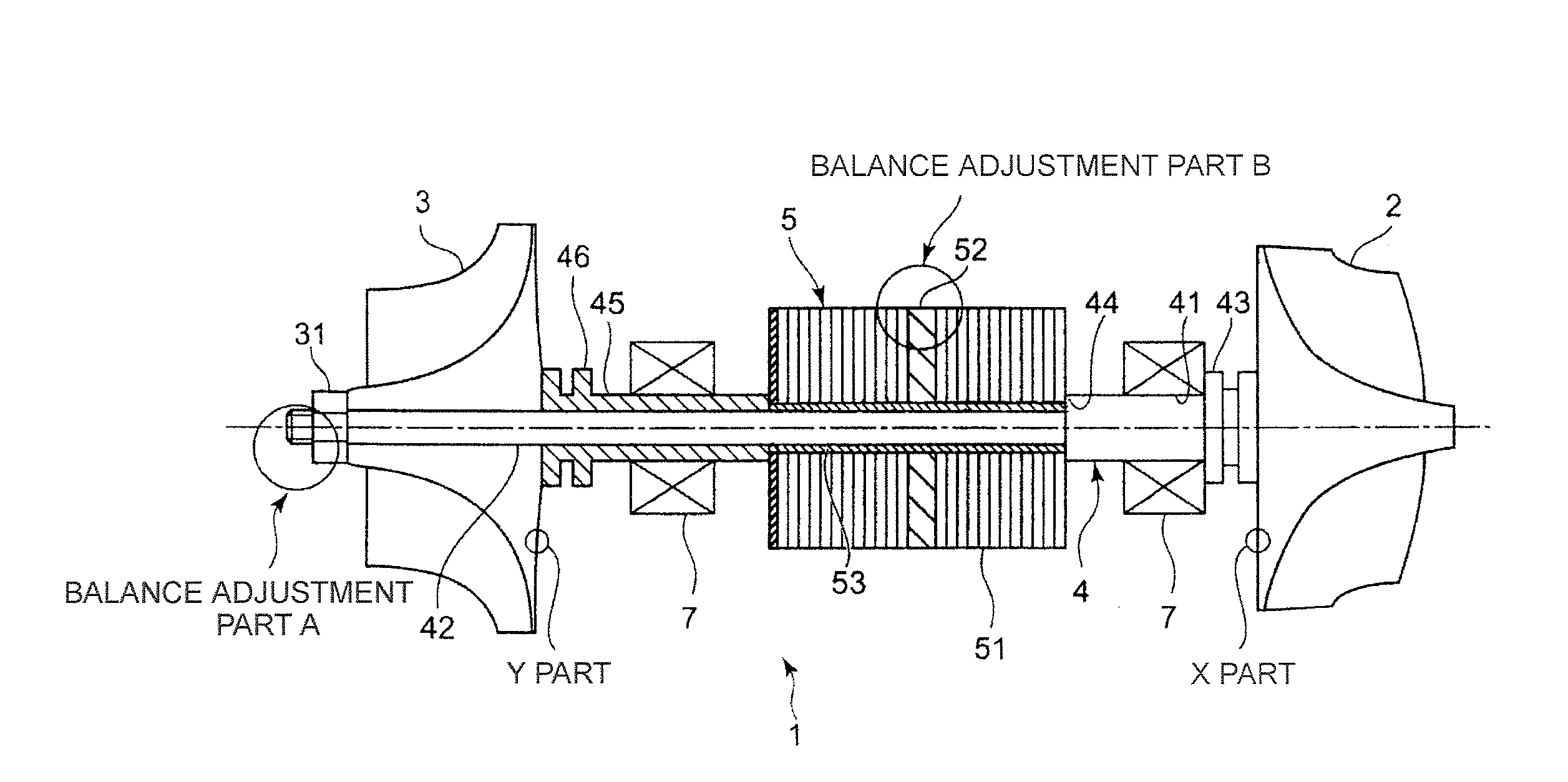
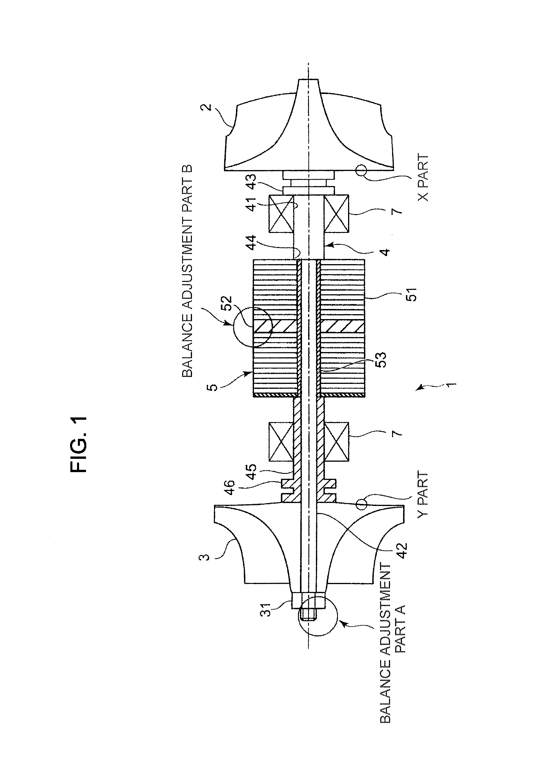
[0049]A turbine rotor according to a first embodiment of the present invention will be described with reference to FIG. 1.

[0050]A turbine rotor 1 includes a shaft 4, a turbine wheel 2 disposed on one end of the shaft 4, a compressor impeller 3 disposed on the other end thereof, two bearings 7 disposed between the turbine wheel 2 and the compressor impeller 3 at intervals, and a rotor core 5 that serves as an electric rotor, and is disposed between the two bearings 7, and the rotor core 5 is mounted on the shaft 4 via a sleeve 53.

[0051]The present invention is applicable to both of a case where the respective bearings 7 are arranged on both outer ends of the rotor core 5 as described above, and a case where the two (pair of) bearings 7 are arranged between the turbine wheel 2 and the rotor core 5 at intervals.

[0052]The shaft 4 is a solid shaft, has a stepped part 44 narrowed from an intermediate part, and is a rotary shaft having a thick portion 41 on one end and a narrow portion 42 ...

second embodiment

[0086]In this second embodiment, components that are identical with those of the first embodiment are denoted by the same reference numerals, and description thereof will be omitted.

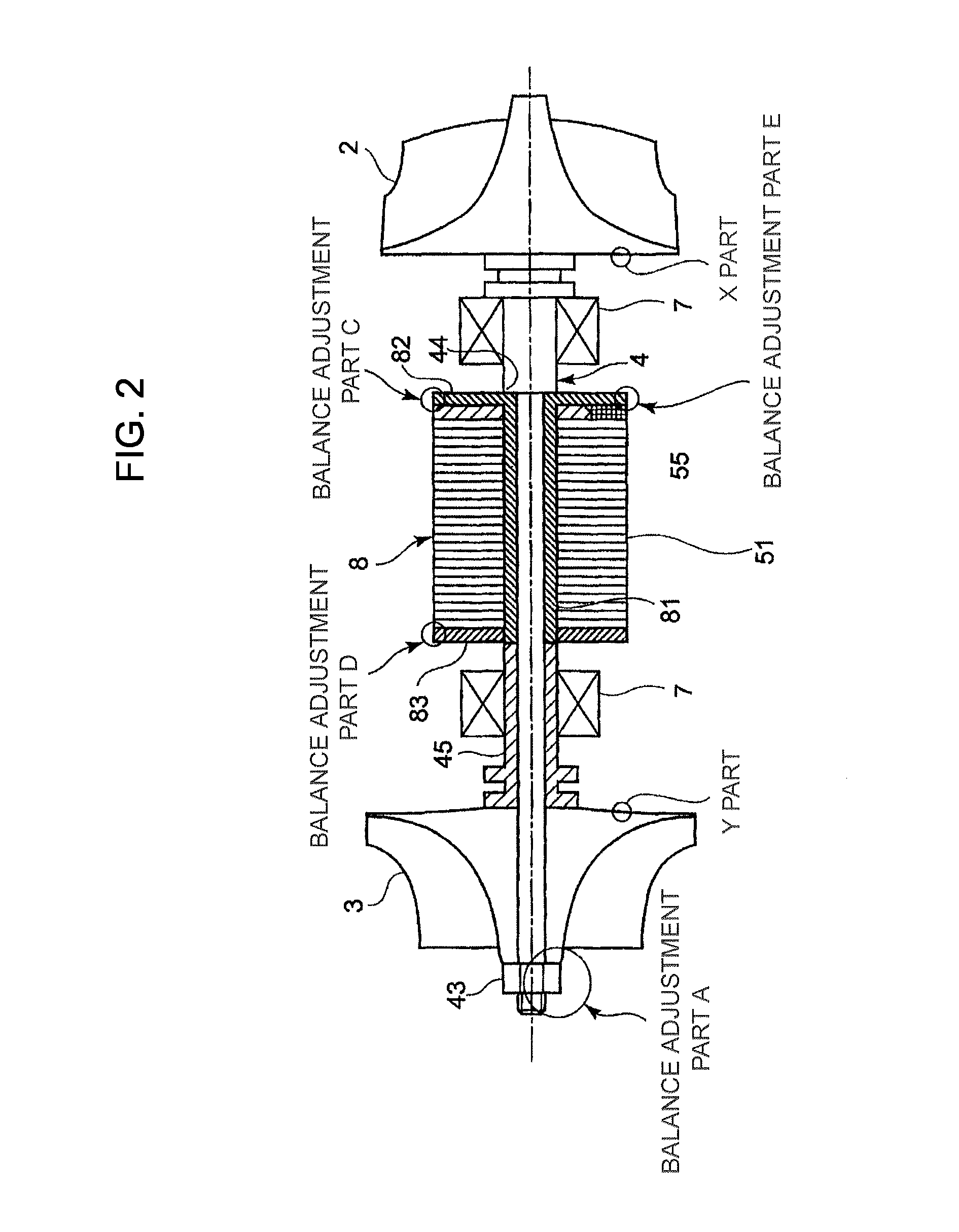
[0087]As shown in FIG. 2, a rotor core 8 is configured such that a plurality of electromagnetic steel plates 51 are disposed on a sleeve 81 fitted onto a narrow portion 42 of a shaft 4.

[0088]The sleeve 81 is formed with a flange part 82 radially from an open edge on one end side of the sleeve 81.

[0089]On the outer peripheral part of the sleeve 81, the electromagnetic steel plates 51 are fitted onto the sleeve 81 so as to be laminated in the thrust direction of the sleeve 81.

[0090]On the other end side of the sleeve 81, a pressing ring 83 is fitted onto the outer peripheral part of the sleeve 81 to be fixed in caulking to the sleeve 81 in a state of pressing the electromagnetic steel plates 51 in the thrust direction.

[0091]Additionally, a center target 55 having an outer diameter substantially identical w...

third embodiment

[0097]In this third embodiment, components that are identical with those of the first and second embodiments are denoted by the same reference numerals, and description thereof will be omitted.

[0098]As shown in FIG. 3, a rotor core 9 is configured such that a plurality of electromagnetic steel plates 51 and a center ring 52 being a rotational balance adjusting member are disposed on a sleeve 81 fitted onto a narrow portion 42 of a shaft 4.

[0099]The sleeve 81 is formed with a flange part 82 radially from an open edge on the one end side of the sleeve 81.

[0100]On the outer peripheral part of the sleeve 81, the electromagnetic steel plates 51 are fitted onto the sleeve 81 so as to be laminated in the thrust direction of the sleeve 81. The center ring 52 being a rotational balance adjusting member is disposed on the intermediate part of the laminated electromagnetic steel plates 51 in the thrust direction of the sleeve 81, particularly on the central part. On the other end side of the v...


PUM


Abstract

An object is to increase portions (increase the amount of correction), where the rotational balance of a rotary shaft of a turbocharging device incorporating an electric motor is adjusted, and to maintain sufficient motor driving force even under a high temperature condition. In a balance adjusting structure for the turbocharging device incorporating an electric motor, a rotor core 5 formed by laminating electromagnetic steel plates 51 is interposed between rotor blades provided on one end or both ends, a rotational balance adjusting member made of iron (magnetic induction member) having a thickens larger than the thickness of each electromagnetic steel plate 51 is disposed on an end of the laminated electromagnetic steel plates 51, or between the laminated layers.

Description

TECHNICAL FIELD[0001]The present invention relates to a structure and a method for adjusting rotational balance of a rotor of a turbocharging device incorporating an electric motor turbocharging suction air to an internal combustion. Herein, the turbocharging device incorporating an electric motor includes a turbo charger incorporating a motor generator, a turbo charger incorporating an electric motor, an electric supercharger, and the like.BACKGROUND ART[0002]Turbo chargers for compressing and turbocharging suction air by driving with exhaust gas of an internal combustion has been widely used, in order to improve output of the internal combustion.[0003]There has been used a turbo charger incorporating a motor generator that improves acceleration responsiveness by incorporating an electric motor in a rotary shaft of the turbocharging device and assisting the acceleration of rotation of a compressor impeller, and collects energy by converting exhaust gas energy into electric energy. ...

Claims


Application Information

Patent Timeline
Patent Type & Authority Applications(United States)
IPC IPC(8): F04D13/06
CPCF02B37/10F02B39/10F02B37/005F01D15/10F01D5/027F05D2220/40H02K7/04H02K7/14H02K15/165Y02T10/12F04D13/06
Inventor YAMASHITA, YUKIOHAYASHI, NORIYUKIIBARAKI, SEIICHIOSAKO, KATSUYUKIEBISU, MOTOKIAN, BYEONGILSUZUKI, HIROSHIARITA, HIDEAKIGOTO, TAKASHIMIYAKE, TOSHIHIKO
Owner MITSUBISHI HEAVY IND LTD
Why Eureka
Try Eureka