Method of forming photoresist pattern
a technology of resist pattern and pattern, which is applied in the direction of photomechanical equipment, instruments, originals for photomechanical treatment, etc., can solve the problems of contaminated surface of the lens of the projection exposure apparatus and reduced resolution
- Summary
- Abstract
- Description
- Claims
- Application Information
AI Technical Summary
Problems solved by technology
Method used
Image
Examples
synthesis example 1
Production of Resin (A′-1)
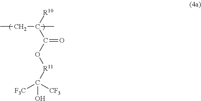
[0117]As the monomers used for preparing the resin (A′-1) including the repeating units shown by the following formula (A′-1), a monomer solution (i) was prepared by dissolving 17.43 g of (1,1,1,3,3,3-hexafluoro-2-propyl)methacrylate and 4.25 g of 2,2-azobis(methyl 2-methylpropionate) in 25 g of methyl ethyl ketone, and a monomer solution (ii) was prepared by dissolving 27.74 g of (1,1,1-trifluoro-2-trifluoromethyl-2-hydroxy-4-pentyl)methacrylate in 25 g of methyl ethyl ketone, respectively. A 500 ml of a three-necked flask equipped with a thermometer and a dropping funnel was charged with 100 g of methyl ethyl ketone, and purged with nitrogen for 30 minutes. After purging with nitrogen, the liquid contained in the flask was heated to 80° C. with stirring using a magnetic stirrer. The monomer solution (i) to be prepared was added dropwise to the flask over 20 minutes using the dropping funnel, aged for 20 minutes, and the monomer solution (ii) to be prepare...
synthesis example 2
Production of Resin (A1-1)
[0120]As the monomer used for preparing the resin (A1-1) including the repeating units shown by the following formula (A1-1), a monomer solution was prepared by dissolving 46.95 g (85 mol %) of (1,1,1-trifluoro-2-trifluoromethyl-2-hydroxy-4-pentyl)methacrylate and 6.91 g of 2,2′-azobis(methyl 2-methylpropionate) which is polymerization initiator in 100 g of isopropyl alcohol (hereinafter referred to as “IPA”). A 500 ml of a three-necked flask equipped with a thermometer and a dropping funnel was charged with 50 g of IPA, and purged with nitrogen for 30 minutes. After purging with nitrogen, the liquid contained in the flask was heated to 80° C. with stirring using a magnetic stirrer. The monomer solution to be prepared was added dropwise to the flask over 2 hours using the dropping funnel. After the addition, the reaction was further performed for 1 hour. After the 10 g of an IPA solution prepared by dissolving 3.05 g (15 mol %) of vinylsulfonic acid in IPA ...
synthesis example 3
Production of Resin (A2-1)
[0123]As the monomer used for preparing the resin (A2-1) including the repeating units shown by the following formula (A2-1), a monomer solution was prepared by dissolving 46.95 g (85 mol %) of 2-methacryloyloxyethyl hexahydrophthalate and 6.91 g of 2,2′-azobis(methyl 2-methylpropionate) which is initiator in 100 g of IPA. A 500 ml of a three-necked flask equipped with a thermometer and a dropping funnel was charged with 50 g of IPA, and purged with nitrogen for 30 minutes. After purging with nitrogen, the liquid contained in the flask was heated to 80° C. with stirring using a magnetic stirrer. The monomer solution to be prepared was added dropwise to the flask over 2 hours using the dropping funnel. After the addition, the reaction was further performed for 1 hour. After the 10 g of an IPA solution prepared by dissolving 3.05 g (15 mol %) of vinylsulfonic acid in IPA was added dropwise to the flask over 30 minutes, the reaction was further performed for 1...
PUM
| Property | Measurement | Unit |
|---|---|---|
| acid | aaaaa | aaaaa |
| area | aaaaa | aaaaa |
| depth | aaaaa | aaaaa |
Abstract
Description
Claims
Application Information
 - R&D
- Intellectual Property
- Life Sciences
- Materials
- Tech Scout
- Unparalleled Data Quality
- Higher Quality Content
- 60% Fewer Hallucinations
Browse by: Latest US Patents, China's latest patents, Technical Efficacy Thesaurus, Application Domain, Technology Topic, Popular Technical Reports.
© 2025 PatSnap. All rights reserved.Legal|Privacy policy|Modern Slavery Act Transparency Statement|Sitemap|About US| Contact US: help@patsnap.com


