
Expanding Blade Screw Retention System

a retention device and expansion blade technology, applied in the field of expansion blade screw retention system, can solve the problems of screw loosening, misplacement of retention device, damage to fusion sight or patient,

Inactive Publication Date: 2014-05-29
RINNER JIM A
View PDF11 Cites 17 Cited by
  • Summary
  • Abstract
  • Description
  • Claims
  • Application Information

AI Technical Summary

Benefits of technology

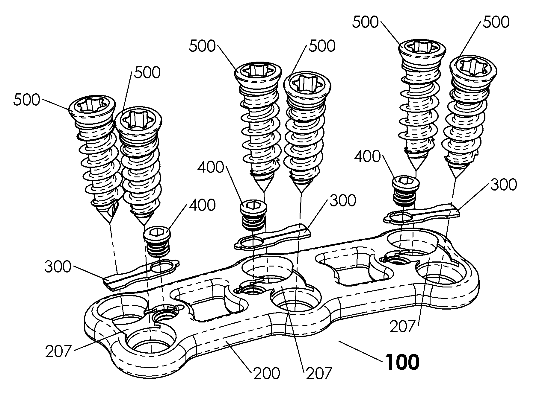
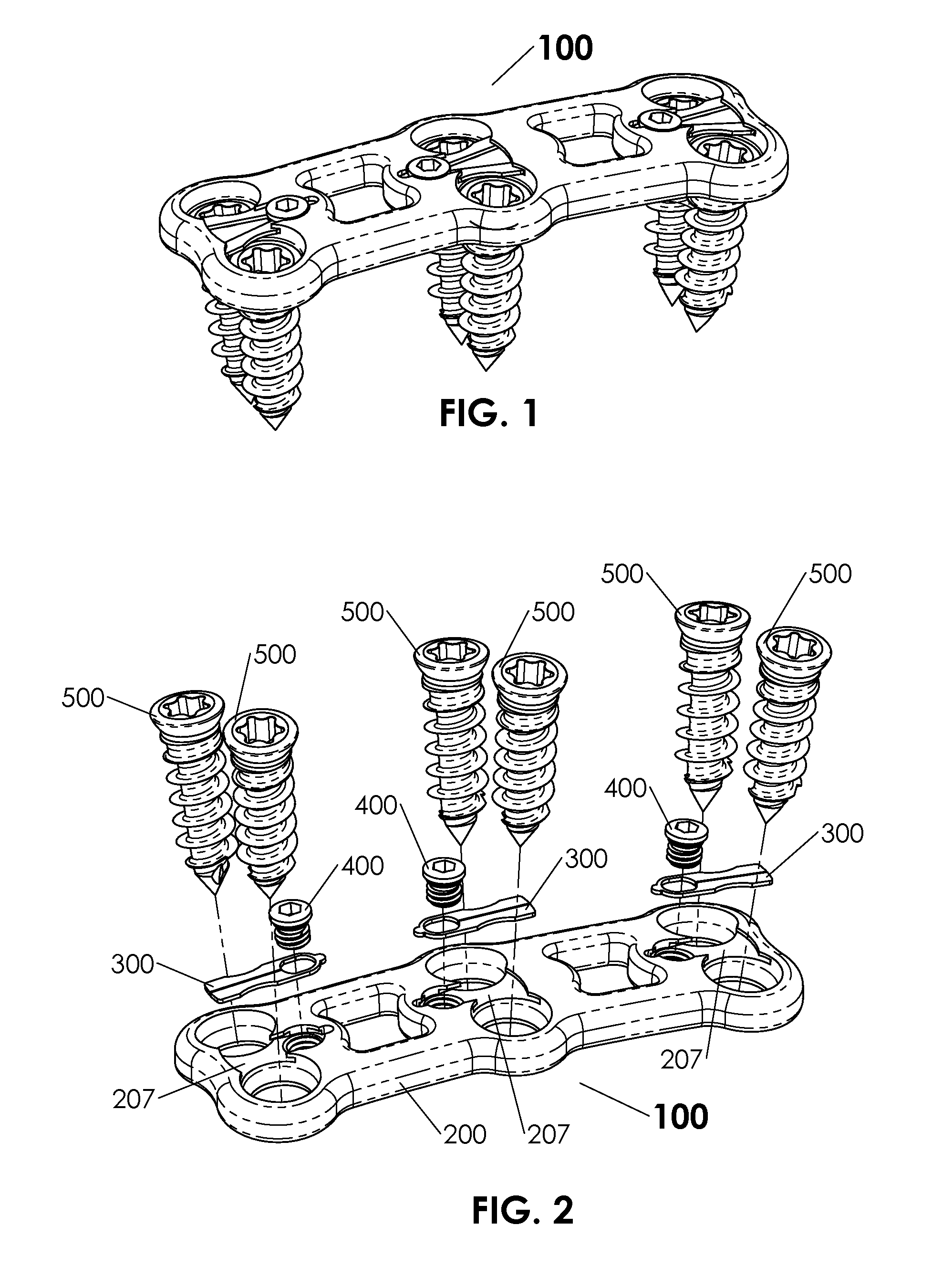
The invention is a cervical spinal fixation system that uses an anterior cervical plate as the base substrate for the retention system. The retention components are placed into position by the manufacturer of the device and are completely assembled prior to the surgery, reducing the chances of misplacement and reducing the amount of time to perform the surgery. In another embodiment, the base, bone screws, retention blade, and / or the retention screw may be pre-assembled by the manufacturer prior to the insertion of the cervical spinal fixation system to the targeted bone segment, allowing the surgeon to attach the cervical spinal fixation system to in-situ to the targeted bone segment and secure the bone screws in a single operation.

Problems solved by technology

Because the bony elements are constantly moving there are forces applied to the fusion construct that can cause the screws to loosen.
If the screws were to loosen to a degree that they would back out of the construct then they could become dislodged and cause harm to the fusion sight or to the patient.
Many systems use additional components that need to be attached after the screws are placed which could cause misplacement of the retention device and failure to retain the screw.

Method used


Image

  • Expanding Blade Screw Retention System
  • Expanding Blade Screw Retention System
  • Expanding Blade Screw Retention System

Examples


embodiment 320

[0052]FIG. 9 is the detailed top view of the dual-bladed retention blade 300. This embodiment of the invention details a dual blade configuration because this embodiment is designed to retain two bone screws 500 simultaneously. It is understood that a single blade embodiment 320, as shown in FIGS. 28, 29, 30 and 31 may operate in the same or a similar manner as the dual blade retention blade 300. It is also understood that any configuration of the retention blade can be manufactured from various types of materials such as, but not limited to, titanium, super-elastic memory metal, polymers or carbon based materials. It is further understood that the manufacturing process used to manufacture the retention blade can be, but not limited to, conventional machining with tool bits, laser cut, water jet or photo etch. The dual blade configuration of the dual-bladed retention blade 300 can include symmetrical surfaces 301, 303, 304, 305, 306, 308, 309 and 310, although non-symmetrical surfac...

embodiment 100

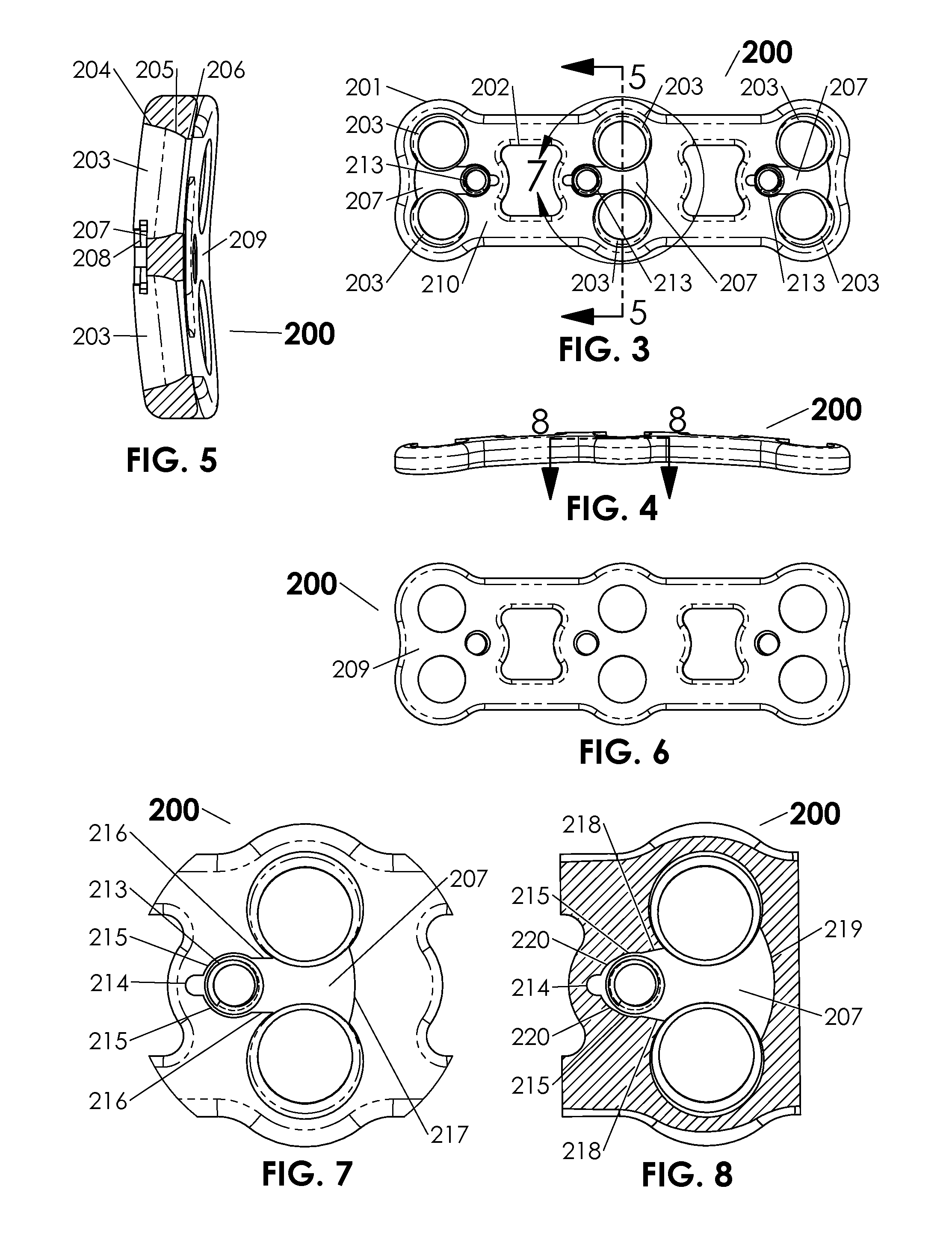
[0072]FIG. 32 is an exploded isometric view of another embodiment of an anterior cervical plate 220 containing a single-bladed embodiment 120 of the invention in the neutral position. For the single-bladed configuration the retention screw 400 and bone screw 500 features can remain the same, if desired, however the anterior cervical plate 220 shown now has a smaller nest than the retention blade nest 207 of the embodiment 100 because the retention feature has only a one-sided retention blade 320 while the prior embodiment of the invention depicted a dual-bladed symmetric design 300.

[0073]FIG. 33 is a top view of another alternative embodiment of a retention blade, specifically a single-bladed retention blade. Instead of the symmetric bladed design of the dual-bladed retention blade 300, the single blade retention blade 320 includes a shorter leg portion 321 that serves a similar functional purpose as the longer leg of the dual-bladed retention blade 300, but including a smaller prof...


PUM


Abstract

Disclosed are devices, systems, methods and surgical techniques for the retention of bone screws used in surgical applications. Various aspects of the invention include features to retain bone screws that are placed in an elongated plate and into a bony member to create a rigid construct and stabilize the member for the purpose of fusion. When the screws are placed through the plate, the retention systems can be engaged to prevent the screws from backing out.

Description

CROSS-REFERENCE TO OTHER APPLICATIONS[0001]This application claims the benefit of U.S. Provisional Patent Application Ser. No. 61 / 730,118 entitled “Expanding Blade Screw Retention System,” filed Nov. 27, 2012, the disclosure of which is incorporated herein by reference in its entirety.TECHNICAL FIELD[0002]The present invention relates to devices, instrumentation, systems and methods that facilitate the retention of bone screws and / or other components in constructs used for various surgical applications. More particularly, the invention includes features that selectively retain bone screws or other anchoring devices that have been introduced through a base member and / or elongated plate and into a patient's bony anatomy. When the screws are advanced through the base member, the retention systems can be engaged, thereby preventing the screws from “backing out” of the member and / or bony anatomy. In various embodiments, the base member can create a rigid construct and stabilize the patie...

Claims


Application Information

Patent Timeline
Patent Type & Authority Applications(United States)
IPC IPC(8): A61B17/86A61B17/80
CPCA61B17/8042
Inventor RINNER, JIM A.
Owner RINNER JIM A
Learn More