
System energy efficiency controller in smart energy network, control method thereof, and control method for terminal device

a smart energy network and controller technology, applied in the direction of process and machine control, computer control, instruments, etc., can solve the problems of inability to adjust the system scale according to user requirements, inability to achieve flexible and robust networking optimization, and inability to achieve economic and social benefits as desired by users. , to achieve the effect of ensuring the accuracy of the control object, speeding up the clearness and veraciousness of the control action, and less demanding communication bandwidth

Active Publication Date: 2014-05-29
ENN SCI & TECH DEV
View PDF4 Cites 13 Cited by
  • Summary
  • Abstract
  • Description
  • Claims
  • Application Information

AI Technical Summary

Benefits of technology

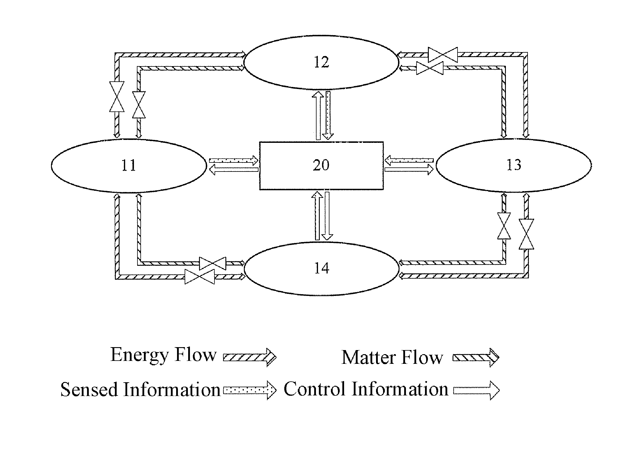
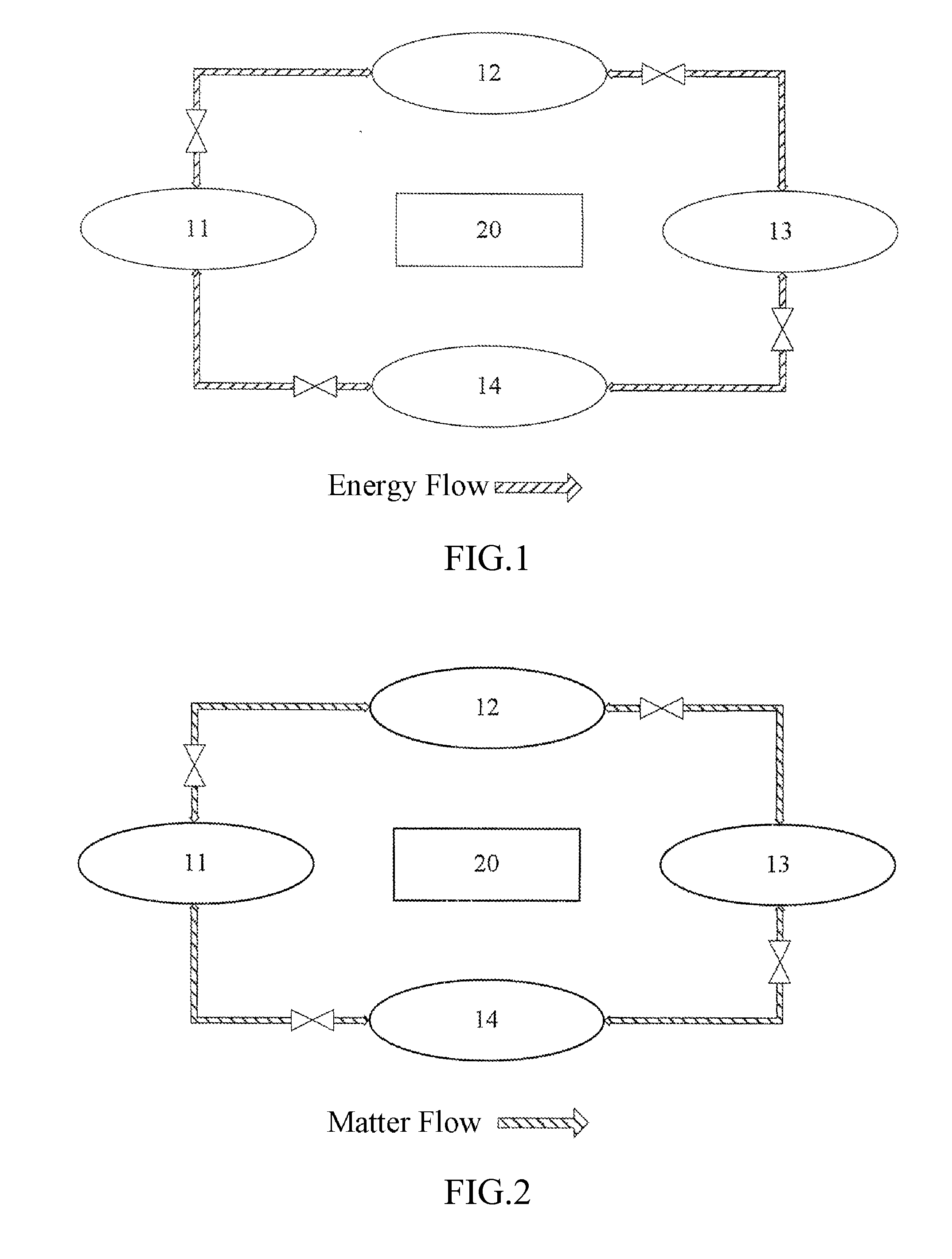
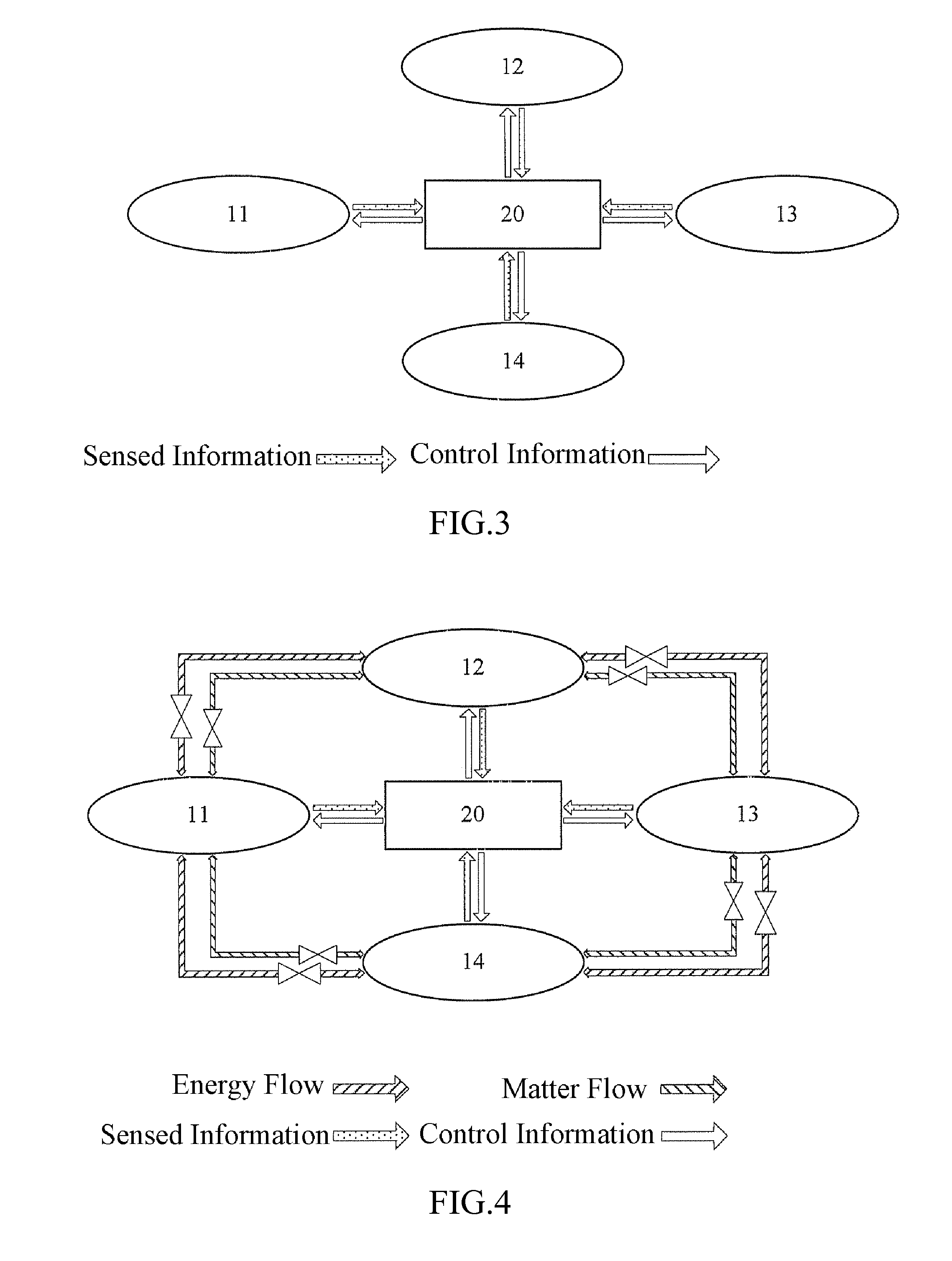
This patent describes a method for controlling a distributed energy system by using a hierarchical information exchange system. This method allows the system to adjust its control strategy based on upper-layer optimization information, while also continuously updating models to ensure accurate control. The method is efficient, fast, and requires less communication bandwidth. It also allows for the in-time reporting of operating information, which can help an upper-layer network better understand the operation of a subsystem and further optimize energy utilization. Additionally, the patent describes how a compact local-area ubiquitous energy network can be easily constructed and how space-domain and time-domain integrated optimization of each stage of energy generation, storage, utilization, and regeneration can be achieved to increase energy utilization efficiency, reduce costs, and achieve a maximum system energy efficiency.

Problems solved by technology

Although the connections of objects are realized by the Smart Planet scheme of IBM, the Smart Planet scheme lacks overall optimization and coordinated control on energy systems, thus the economic and social benefits as desired by users cannot be fully realized.
Furthermore, the Smart Planet scheme entirely depends on the coverage rate of the Internet of Things and the existing Internet, and has a flat, large and complicated network structure, as a result, it is impossible to change the system scale according to user requirements and achieve flexible and robust networking optimization.

Method used


Image

  • System energy efficiency controller in smart energy network, control method thereof, and control method for terminal device
  • System energy efficiency controller in smart energy network, control method thereof, and control method for terminal device
  • System energy efficiency controller in smart energy network, control method thereof, and control method for terminal device

Examples


Embodiment Construction

[0040]First of all, the terms used in this application will be illustrated as follows:

[0041]A system energy efficiency refers to the energy utilization efficiency or effect in a system, which includes a group of parameters for evaluating the utilization effect of the system on the grade and quantity of energies, for example, a thermal efficiency, an electrical efficiency, an exergy efficiency, etc. An important improvement of the system energy efficiency is the matching of the grade and quantity of energy supply with demands, which improves people's energy generation mode and energy utilization mode.

[0042]A ubiquitous energy network is formed by nodes that are connected together via a virtual pipeline interconnected network architecture for transmitting a ubiquitous energy flow, with ubiquitous energy flows being bidirectionally transmitted between the nodes. The nodes include a system energy efficiency controller, and at least one from a group consisted of other nodes connected to ...


PUM


Abstract

A system energy efficiency controller in a smart energy network, a control method thereof, and a control method for a terminal device. The system energy efficiency controller includes a control decision module, a storage module, a power clock module, an internal communication module, and an external communication module. The storage module is connected to the control decision module, and stores temporary and permanent information data in the operation process of the storage system. The power clock module provides an internal clock, achieving timing synchronization of processors on the controller. The internal communication module provides two-way communication between the system energy efficiency controller and control implementation units of multiple terminal devices. The external communication module provides two-way communication between the system energy efficiency controller and a local optimizer. The multiple terminal devices include at least one of the terminal devices for the stages of energy production, storage, application and regeneration.

Description

FIELD OF THE INVENTION[0001]The present invention relates to a system energy efficiency controller and a system control method for realizing optimized utilization of energies, and in particular, to a system energy efficiency controller and a system control method used in a ubiquitous energy network for realizing optimized utilization of distributed energies.BACKGROUND OF THE INVENTION[0002]One of essential aspects to realize low-carbon economy lies in improving the overall utilization efficiency of energies. By combining the existing power grid with network communication technologies, the intelligentized generation, transmission and utilization of an electrical energy may be achieved. A basic characteristic of a smart power grid is technology informationization, automation and interaction. An interactive power grid proposed by a Chinese scholar named Jiandong W U implements intelligentized, informationized, and hierarchical interactive management on the overall process of the electr...

Claims


Application Information

Patent Timeline
Patent Type & Authority Applications(United States)
IPC IPC(8): G05B15/02
CPCG06Q50/06G06Q10/06313Y04S20/221G05B15/02H02J13/00017H02J13/00028Y02B70/30Y02E60/00Y02P80/10Y04S40/124Y04S20/00Y04S20/222Y02B70/3225Y02B90/20H02J13/00007H02J13/00026Y04S40/126Y04S40/121Y04S10/30Y02E40/70Y04S10/50
Inventor GAN, ZHONGXUEDONG, SHENGLONGCAI, QIZHI
Owner ENN SCI & TECH DEV
Learn More