
Dual Crane Apparatus and Method of Use

Active Publication Date: 2014-06-05
ARTHUR BRADY PAUL +1
View PDF75 Cites 12 Cited by
  • Summary
  • Abstract
  • Description
  • Claims
  • Application Information

AI Technical Summary

Benefits of technology

The disclosed apparatus is a unique solution for servicing mobile irrigation systems. It is designed as a dual crane system that can be easily transported to a field and operated by one user to change a tire or repair other components of the system. The apparatus includes a handheld control for convenient operation and a carrying area for tools and equipment needed for servicing. It also includes a spare tire or gearbox carrying area, making it convenient to transport such items to and from the mobile irrigation system. The unique design also reduces the risk of injury by eliminating the need for dangerous jacks. Overall, the apparatus simplifies and makes the servicing process more efficient and safe.

Problems solved by technology

Such a task is practically impossible without the help of multiple people.
The tires are extremely heavy and are often stuck in mud, making it even more difficult to remove the tires.
Such boards, however, quickly become muddy and slippery and create a surface on which the jack easily slides off.
This process is so dangerous that those skilled in the art commonly refer to such jacks as “widow makers.” Obviously, changing a tire on a mobile irrigation system is a labor intensive, strenuous and dangerous undertaking.
Like changing a tire, changing a gearbox on a mobile irrigation system is a labor intensive, strenuous and dangerous undertaking.
As one can see, current methods used to repair or replace tires and gearboxes on mobile irrigation systems are difficult, unsafe, and time-consuming.
It is impractical to attempt to manually carry a tire or even a gearbox to and from a tower in the field.
Plus, the task is made even more challenging when you consider that the soil has been irrigated and the farmer or repairman is forced to trudge through a soft and muddy field to reach the portion of the mobile irrigation system in need of service.

Method used


Image

  • Dual Crane Apparatus and Method of Use
  • Dual Crane Apparatus and Method of Use
  • Dual Crane Apparatus and Method of Use

Examples


Embodiment Construction

[0031]The terms “top,”“bottom,”“front,” and “rear” are used in the specification to describe the embodiments of the invention as illustrated in the accompanying Figures. It should be appreciated that in actual use, an embodiment of the invention may be rotated as needed to accomplish the objectives of the invention. As a result of such rotation, the various terms used herein of “top,”“bottom,”“front,”“rear,” and the like may not literally apply to a particular arrangement. Such terms are relative and are used herein to describe the Figures for illustration purposes only and are not intended to limit the embodiments shown to any particular orientation.

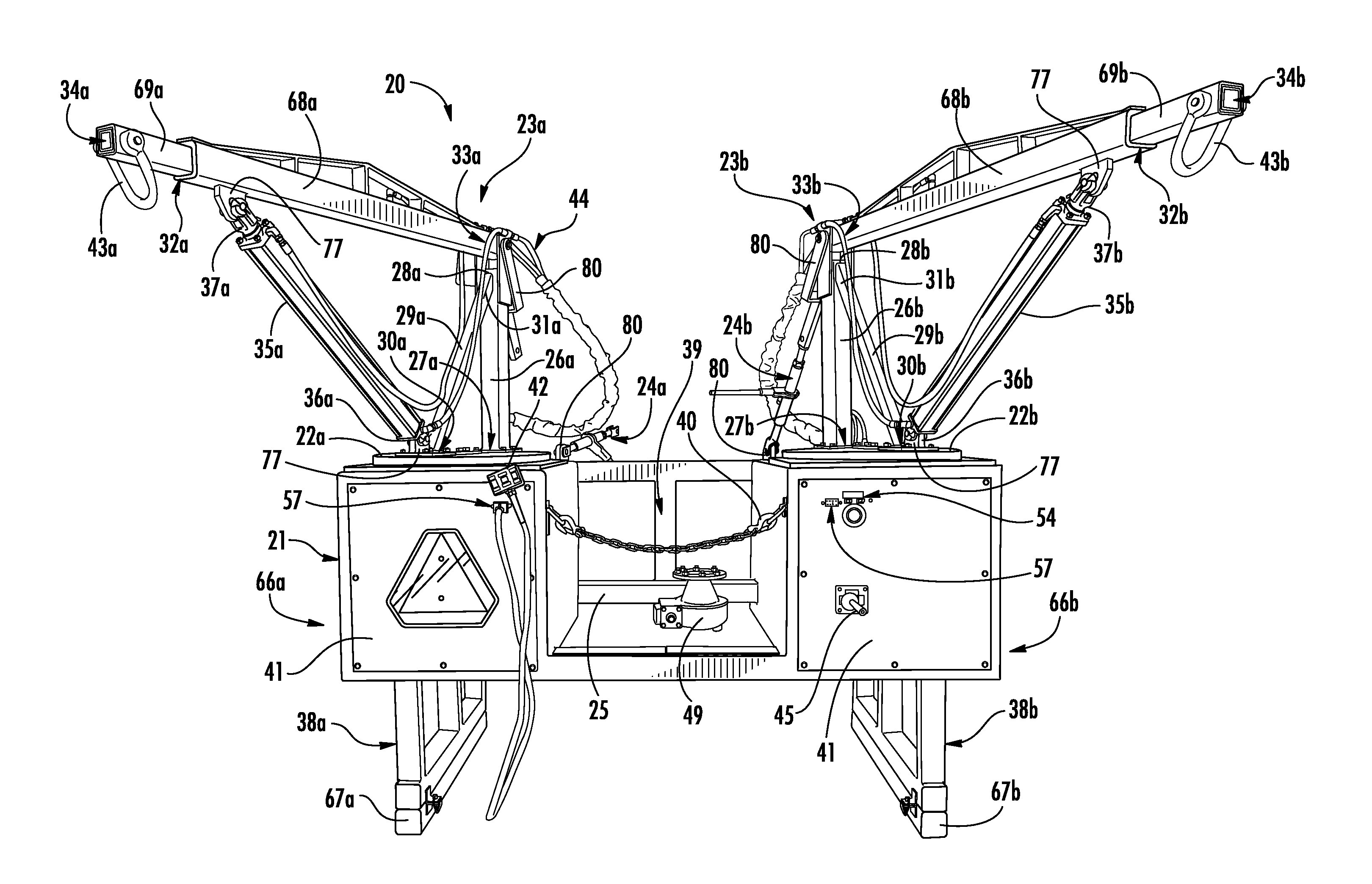
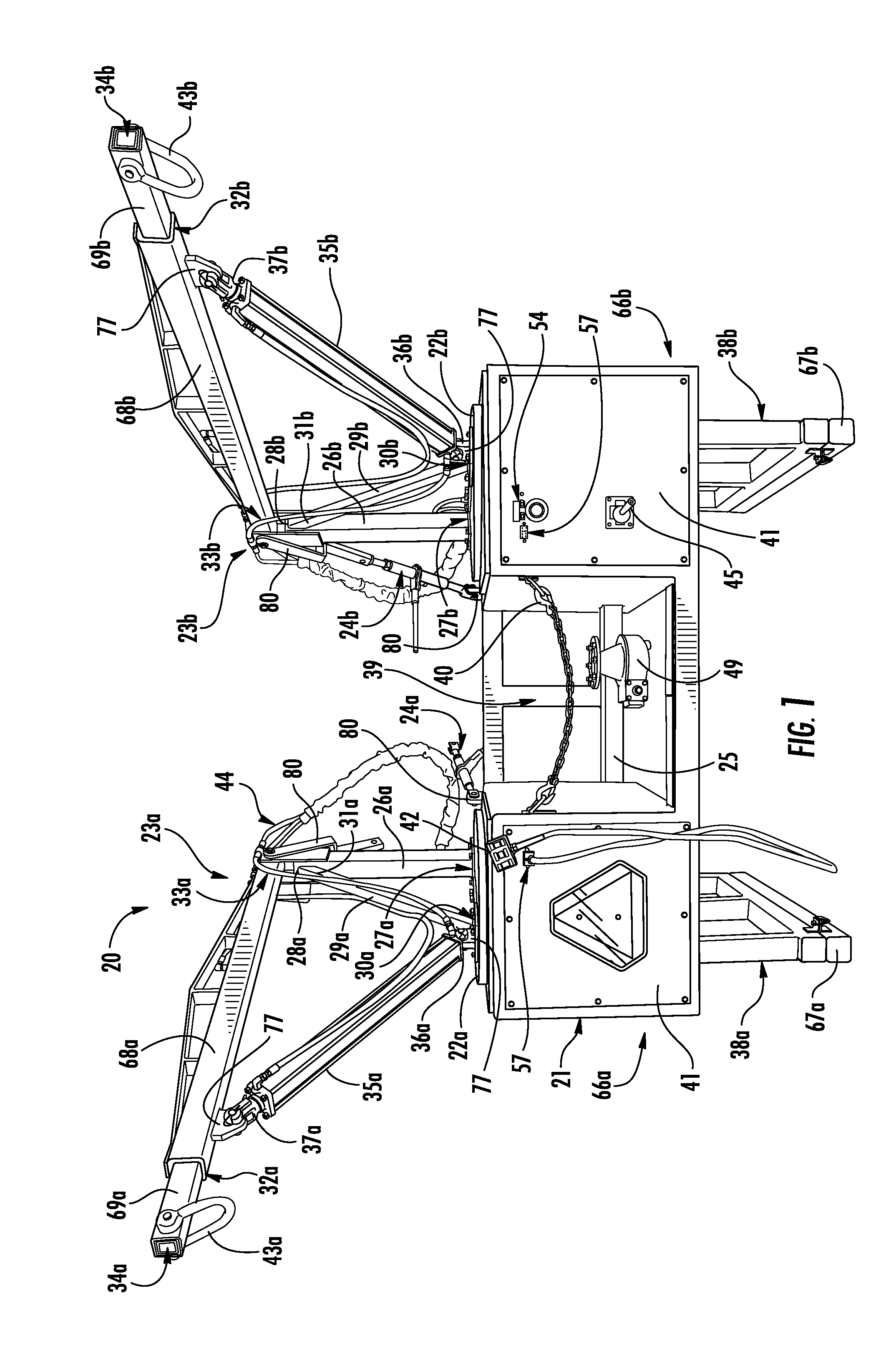
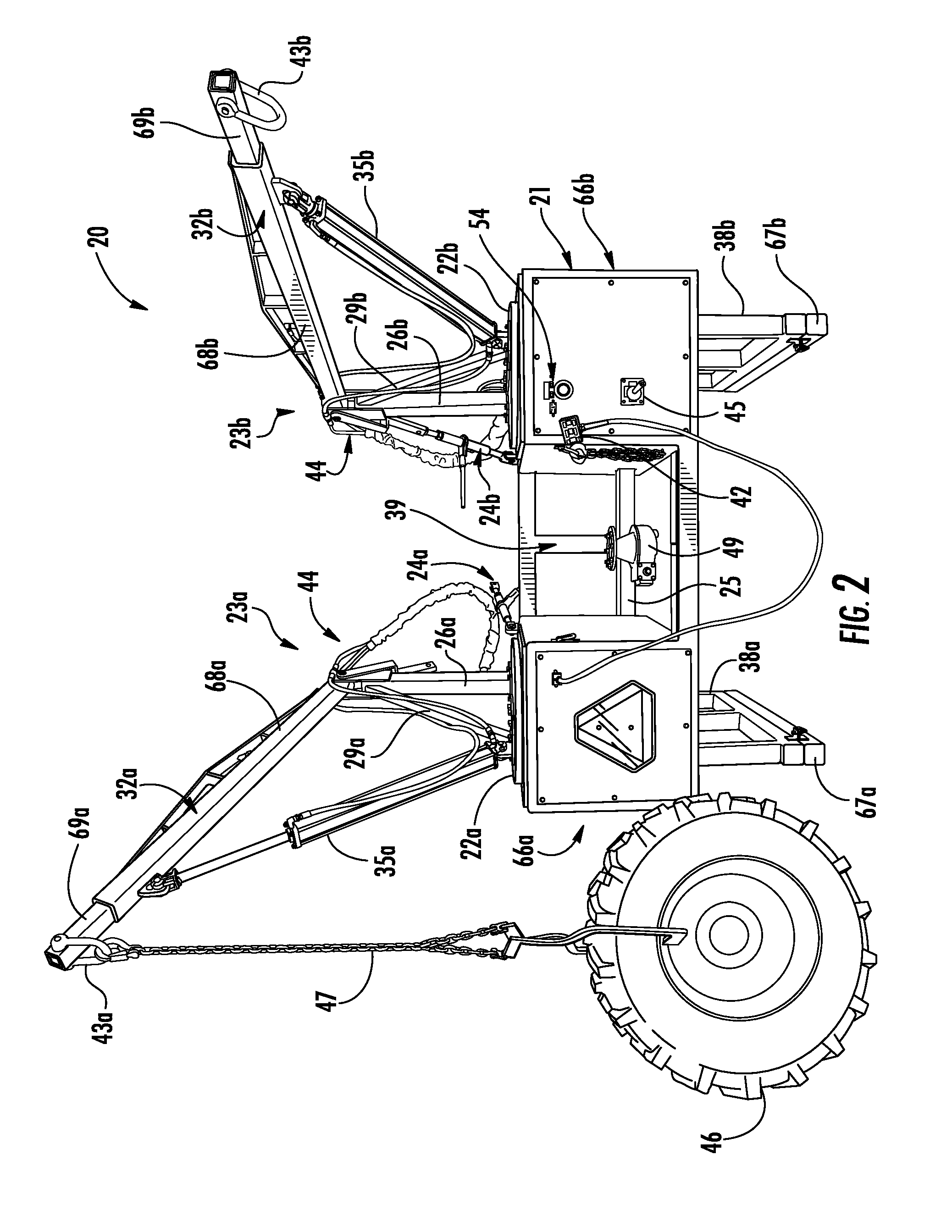
[0032]Referring now to FIGS. 1-11, exemplary embodiments of a dual crane apparatus 20 and methods of use in accordance with the present disclosure are illustrated.

[0033]Turning to the Figures for illustrative purpose, FIG. 1 is a front view of a dual crane apparatus 20 according to the present disclosure. The apparatus 20 depicted in FI...


PUM

PropertyMeasurementUnit
Angleaaaaaaaaaa
Areaaaaaaaaaaa
Heightaaaaaaaaaa

Abstract

A dual crane apparatus and a method of use are disclosed herein. The disclosed dual crane apparatus generally comprises a support frame and two rotating crane members mounted to the support frame, wherein the crane members can each independently move up and down in a vertical direction, extend and retract in a horizontal direction, and rotate clockwise and counterclockwise. The disclosed dual crane apparatus can be utilized for servicing mobile irrigation systems.

Description

CROSS-REFERENCE TO RELATED APPLICATIONS[0001]This application is related to and claims priority from earlier filed U.S. Provisional Patent Application No. 61 / 733,477, filed Dec. 5, 2012, the disclosure of which is incorporated herein by reference.BACKGROUND OF THE INVENTION[0002]1. Field of the Invention[0003]The present invention generally relates to a dual crane apparatus and method of use. More specifically, the present invention relates to a dual crane apparatus for servicing mobile irrigation systems.[0004]2. Description of Related Art[0005]Mobile, self-propelled irrigation systems, such as center-pivot or lateral move irrigation systems, are commonly used to irrigate large fields of row crops. These mobile irrigation systems are generally comprised of a plurality of irrigation pipes joined together to form an elongated tubular member supported at various points along its length by wheeled drive towers, which support and propel the irrigation pipe over fields. The irrigation pi...

Claims


Application Information

Patent Timeline
IPC IPC(8): B66C23/18B66C23/00
CPCB66C23/54B66C23/18B66C23/00Y10T29/4973
Inventor ARTHUR, BRADY PAULARTHUR, DAVID LLOYD
Owner ARTHUR BRADY PAUL
Learn More