Failsafe magnetorheological (MR) energy absorber

a magnetorheological and damper technology, applied in the field of failure-safe magnetorheological dampers, can solve the problems of inability to automatically adapt the energy absorption as a function of payload weight or real-time environmental measurements, severe wave-to-hull impact of high-speed watercraft, and the like. achieve the effect of reducing the stroking load of the lwr mrea, and increasing or reducing the baseline magnetic field

Active Publication Date: 2014-06-05
INNOVITAL LLC +1
View PDF12 Cites 38 Cited by
  • Summary
  • Abstract
  • Description
  • Claims
  • Application Information

AI Technical Summary

Benefits of technology

[0014]In the LWP MREA a cup-shaped rotor is mounted on a shaft inside a hollow MR-fluid-filled housing, and is free to rotate on the shaft inside the housing. A stationery stator body occupies the center of the housing inside the cup-shaped rotor. The rotor shears the MR fluid, and the shear resistance of the MR fluid is controlled by changing the rheological properties of the fluid with the presence of a magnetic field, allowing control over the reaction force on the rotor, which in turn causes a reaction torque-moment on the shaft. The torque-moment serves as a damping force and can be further converted into a linear damping force with a rotary-to-linear motion converting mechanism. In one embodiment, the magnetic field is created by a combination of permanent magnets in the stator body which create a baseline magnetic bias, plus

Problems solved by technology

Severe shock events may include harsh vertical or crash landings of aircraft, under body explosions of military ground vehicles, horizontal collisions of automobiles, and severe wave-to-hull impact of high speed watercraft.
Lower amplitude shock and vibration tend to result from normal operation of such vehicles, including aircraft air loads or rotor loads, ground vehicles traversing rough terrain, etc.
Most current shock and vibration protection systems are passive, in that they cannot automatically adapt their energy absorption as a function of payload weight or as a function of real-time environmental measurements such as shock level, impact velocity, vibration levels, etc.
Because of this, these systems provide no isolation of vibration.
Even during normal operation whole body vibration (

Method used


Image

  • Failsafe magnetorheological (MR) energy absorber
  • Failsafe magnetorheological (MR) energy absorber
  • Failsafe magnetorheological (MR) energy absorber

Examples


Embodiment Construction

[0028]Generally, the invention disclosed herein is a novel compact and failsafe magnetorheological energy absorber design including both a light weight piston (LWP) embodiment in which linear motion is subjected to a rotary damping force, and a light weigh rotary vane (LWRV)embodiment in which linear motion is converted into rotary motion and is subjected to a rotary damping force. Both embodiments allow increased damper stroke within a compact mechanical profile. A new lightweight Magnetorheological energy attenuation system (LMEAS) for a vehicle seat is also disclosed using the new LMRW MREA mentioned above.

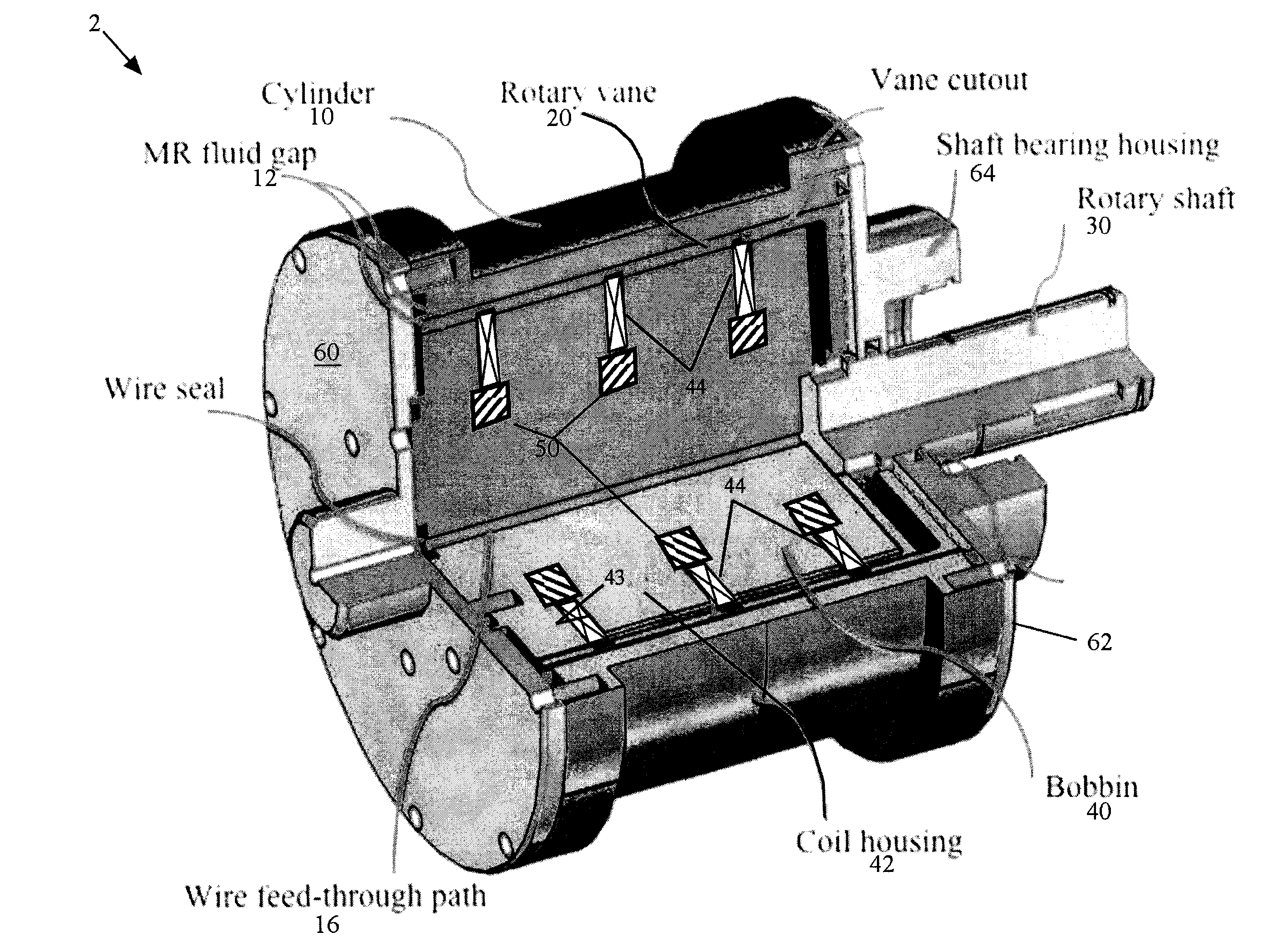
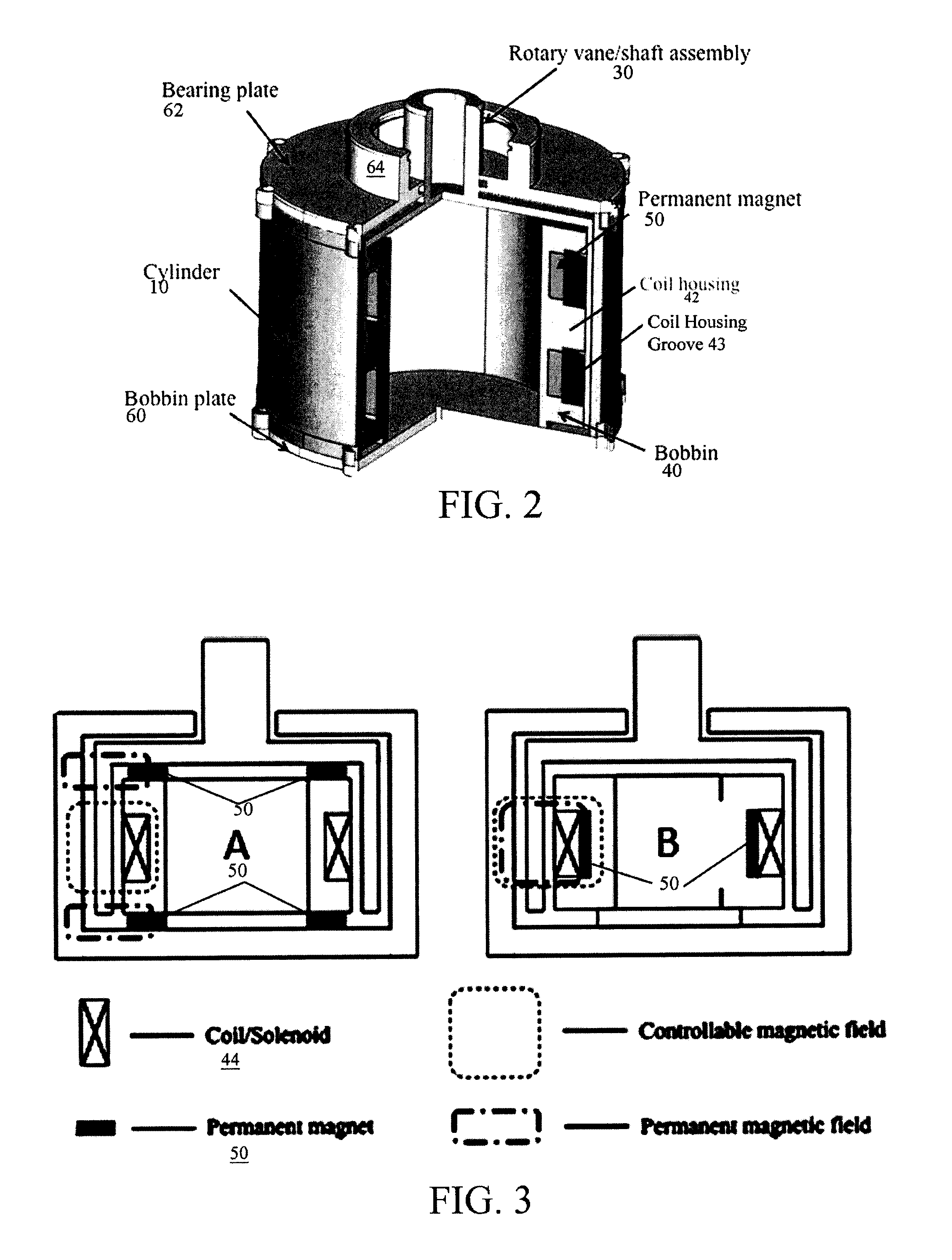
[0029]A first embodiment is a lightweight rotary vane (LWRV) magnetorheological energy absorber (MREA) as depicted in FIG. 1. In this embodiment, the LWRV MREA 2 comprises a cylindrical damper housing 10 defining an internal cylindrical volume containing MR fluid. Damper housing 10 is capped by opposing end plates including a lower coil bobbin plate 60 and upper bearing plate 6...


PUM


Abstract

A compact and failsafe magnetorheological energy absorber design including both a light weight piston (LWP) embodiment in which linear motion is subjected to a linear damping force, and a light weight rotary vane (LWRV)embodiment in which linear motion is converted into rotary motion and is subjected to a rotary damping force. Both embodiments allow increased damper stroke within a compact mechanical profile. A new lightweight Magnetorheological energy attenuation system (LMEAS) for a vehicle seat is also disclosed using the new LMRW MREA.

Description

CROSS-REFERENCE TO RELATED APPLICATION(S)[0001]The present application derives priority from U.S. Provisional Patent Application 61 / 658,463 filed Jun. 12, 2012.BACKGROUND OF THE INVENTION[0002]1. Field of the Invention[0003]The present invention relates generally to energy absorbers and energy absorption systems, and more particularly, to a failsafe magnetorheological damper for shock and vibration energy absorption systems employing a combination of permanent or switchable magnets with electromagnetic coils.[0004]2. Description of Prior Art[0005]The primary function of a shock and vibration protection system is to minimize the potential for equipment damage and / or personnel injury during shock and vibration loading. Such systems are important for vehicular applications, including aircraft, ground vehicles, marine vehicles, etc. Severe shock events may include harsh vertical or crash landings of aircraft, under body explosions of military ground vehicles, horizontal collisions of au...

Claims


Application Information

Patent Timeline
IPC IPC(8): F16F9/53B60N2/52B60N2/50
CPCF16F9/535B60N2/501B60N2/522F16F9/12
Inventor HIEMENZ, GREGORY J.WERELEY, NORMAN M.
Owner INNOVITAL LLC
Why Eureka
Try Eureka