LED lighting apparatus, current regulator for the LED lighting apparatus, and current regulation method of the LED lighting apparatus

a technology of led lighting and current regulator, which is applied in the direction of energy-efficient lighting, sustainable building, and semiconductor lamp usage, can solve the problems of reduced total power efficiency, complicated construction, and conventional led lighting apparatus, and achieves efficient power supply, simple structure, and high power efficiency

Active Publication Date: 2014-06-05
SILICON WORKS CO LTD
View PDF18 Cites 21 Cited by
  • Summary
  • Abstract
  • Description
  • Claims
  • Application Information

AI Technical Summary

Benefits of technology

[0014]Another object of the present invention is to provide an LED lighting apparatus having a simple structure and high power efficiency by supplying a power to an LED lighting and peripheral circuit modules, such as a sensor board and a communication module, in common using a current regulator, a current regulator for the LED lighting apparatus, and the current regulation method of the LED lighting apparatus.
[0015]Yet another object of the present invention is to provide an LED lighting apparatus capable of efficiently supplying a power to a peripheral circuit module, such as a communication module for controlling a plurality of LED lightings spaced apart from one another, such as security lights or streetlamps.

Problems solved by technology

However, the conventional LED lighting apparatus is disadvantageous in that it has a complicated construction because the conventional LED lighting apparatus includes the SMPS module for supplying a power to an LED lighting and the driving circuit for driving LEDs using a current driving method.
As described above, the conventional LED lighting apparatus has a problem in that total power efficiency is reduced due to the complicated construction.
In such a case, most of power is consumed by the driving circuit for driving LEDs.
Accordingly, the conventional LED lighting apparatus is problematic in that power efficiency for the additional peripheral circuit modules is low because most of power is consumed by the driving circuit for driving LEDs.

Method used


Image

  • LED lighting apparatus, current regulator for the LED lighting apparatus, and current regulation method of the LED lighting apparatus
  • LED lighting apparatus, current regulator for the LED lighting apparatus, and current regulation method of the LED lighting apparatus
  • LED lighting apparatus, current regulator for the LED lighting apparatus, and current regulation method of the LED lighting apparatus

Examples


Embodiment Construction

[0027]Reference will now be made in greater detail to a preferred embodiment of the invention, an example of which is illustrated in the accompanying drawings. Wherever possible, the same reference numerals will be used throughout the drawings and the description to refer to the same or like parts.

[0028]An embodiment of the present invention has a structure having improved power efficiency because a power is driven using a current regulator 30.

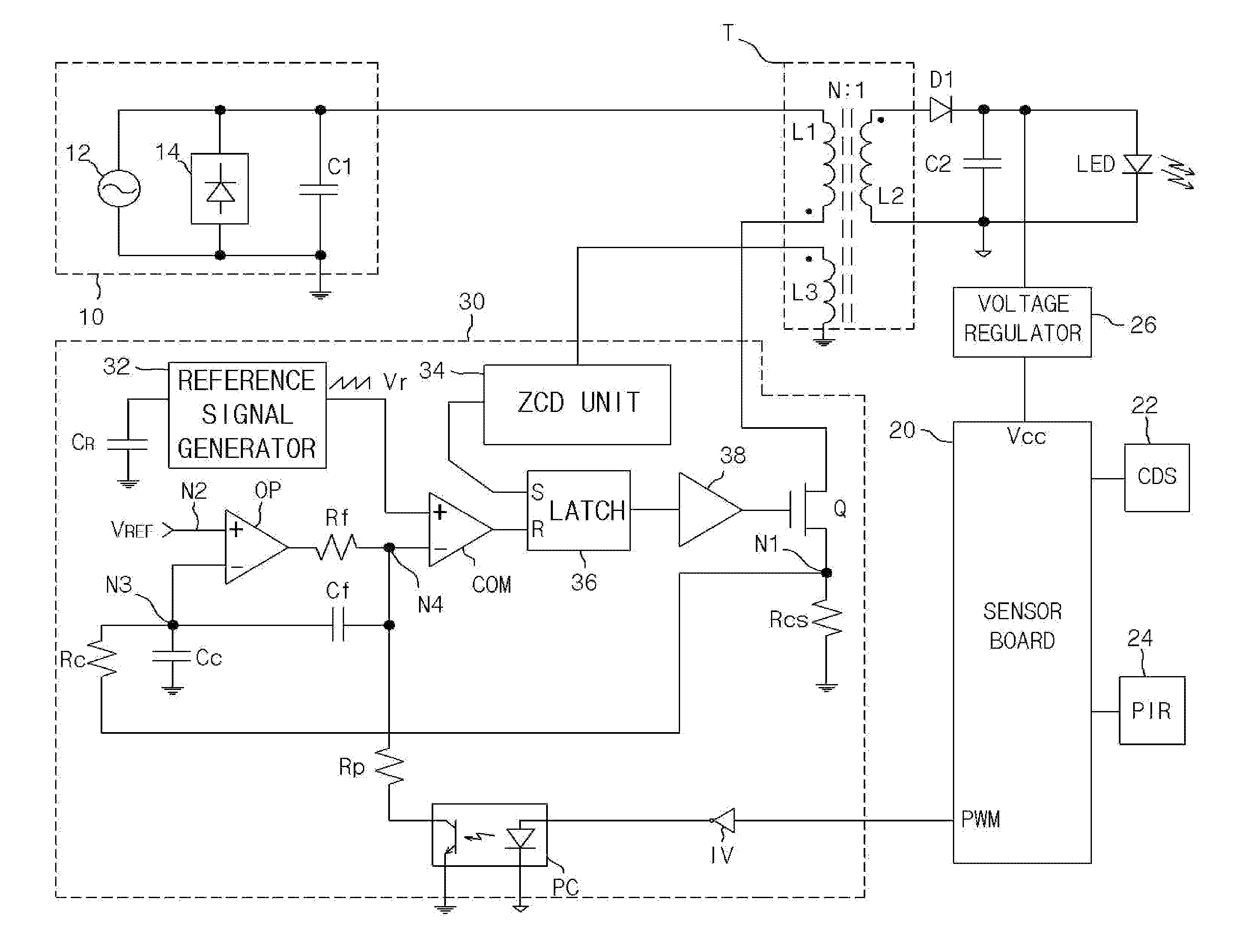
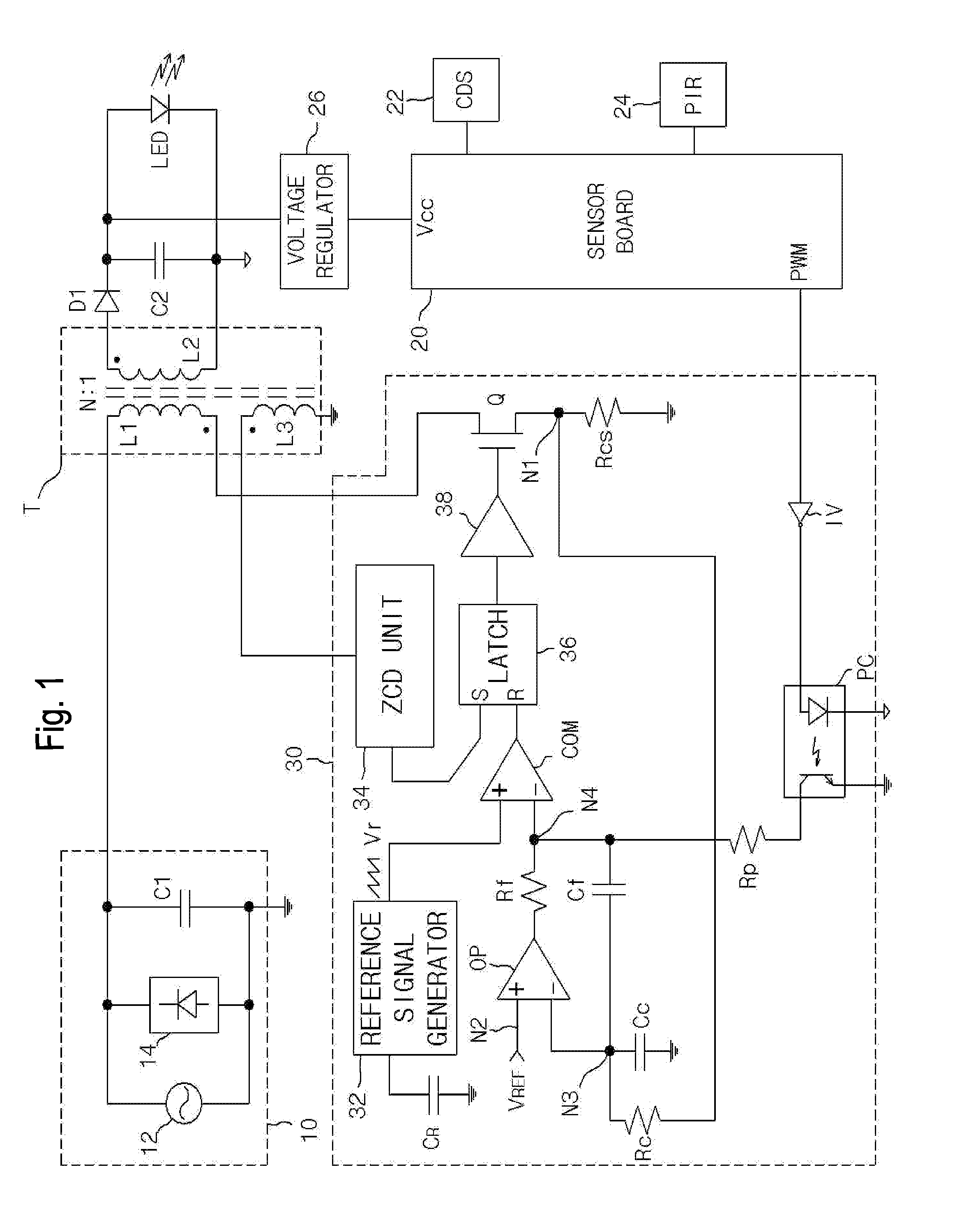
[0029]Referring to FIG. 1, an LED lighting apparatus in accordance with an embodiment of the present invention includes a power source unit 10, a transformer T, a sensor board 20, and the current regulator 30.

[0030]The power source unit 10 is configured to perform full-wave rectification on AC power and output the results of the full-wave rectification as rectified voltage. That is, the power source unit 10 has a structure in which a power source 12, a rectification circuit 14, and a capacitor C1 are connected in parallel.

[0031]The power sourc...


PUM


Abstract

The present invention discloses an LED lighting apparatus. The LED lighting apparatus includes a converter for transforming rectified voltage in accordance with a switching operation according to a driving pulse and outputting the transformed voltage, a current regulator for generating the driving pulse having a pulse width varied in response to a control signal and the amount of current of the converter and switching the operation of the converter using the generated driving pulse, and a peripheral circuit module for providing the control signal for controlling the dimming of an LED lighting.

Description

BACKGROUND OF THE INVENTION[0001]1. Field of the Invention[0002]The present invention relates to a Light-Emitting Diode (hereinafter referred to as an ‘LED’) lighting apparatus, and more particularly, to an LED lighting apparatus having improved power efficiency, a current regulator for the LED lighting apparatus, and the current regulation method of the LED lighting apparatus.[0003]2. Description of the Related Art[0004]In recent lighting apparatuses, incandescent lights and fluorescent lights are being replaced with LEDs capable of being implemented to have a relatively longer lifespan, low consumption power, and high brightness as lighting lamps.[0005]The lighting apparatus may include, for example, a security light and a streetlamp. An LED lighting apparatus that adopts an LED lighting is also developed as the security light or streetlamp and commercialized.[0006]In general, a conventional LED lighting apparatus is implemented using a Switching Mode Power Supply (hereinafter ref...

Claims


Application Information

Patent Timeline
Patent Type & Authority Applications(United States)
IPC IPC(8): H05B33/08H05B44/00
CPCH05B45/14H05B47/185Y02B20/30H05B45/3725H05B45/382H05B45/12Y02B20/72
Inventor KIM, YONG GUENLEE, SANG YOUNGMUN, GYEONG SIKAN, KI CHUL
Owner SILICON WORKS CO LTD
Why Eureka
Try Eureka