Transversely-activated valve for a therapeutic vaporizer bag attachment system

a technology of transverse activation and valve, which is applied in the field of therapeutic vaporizer inhalation bag attachment system, can solve the problems of unsightly existing devices, limited control of the vaporization process, and large vaporizer bags, etc., and achieves the effects of improving the quality of vaporization gas

Inactive Publication Date: 2014-06-12
PRATT ROBERT IRVING JR
View PDF10 Cites 83 Cited by
  • Summary
  • Abstract
  • Description
  • Claims
  • Application Information

AI Technical Summary

Benefits of technology

[0007]Some embodiments described herein generally relate to devices for vaporizing therapeutic materials. In some embodiments, the devices disclosed herein improve upon or overcome flaws and deficiencies in existing devices that have been recognized by the instant inventors. Specifically, some existing devices are unsightly, large, cumbersome, inefficient, expensive, and / or difficult to use. Furthermore, some devices also have limited control of the vaporization process, and thus produce a poor quality of therapeutic gas. Some conventional devices also include bulky accessories attached to the heater unit that can become tangled, or if detachable, lost. Some embodiments disclosed and described herein overcome the various drawbacks and deficiencies, for example, by being simpler to use, while providing a higher quality therapeutic gas. Some embodiments herein relate to a bag attachment system that captures the vaporized gas from which the user can subsequently control the release of the vaporized gas for inhalation. Some embodiments relate to a vaporizer bag attachment system with a valve to control flow of gas to and from a bag. Some embodiments relate to a vaporizer attachment system that includes a transversely-actuated duck-bill valve. The attachment system can include a unitary, monolithic, compact, rugged design that includes a mouthpiece, body and valve, in some embodiments, without additional components other than a coupling to connect the body of the system to a bag. The resulting compact, one-piece design, is comfortable, easy to use, easily cleaned, rugged, and free of additional loose parts that can be. The system can be durable, resistant to high temperature, resistant to leaking when attached to a bag, and / or simple and intuitive to operate. The attachment systems described herein can include a valve that automatically closes when removed from a therapeutic vaporizer, but without requiring additional, external components to reopen the valve and inhale vapors from a bag attached to the attachment system. The attachment systems herein include a valve that can be manually opened by a user, including a physically impaired user, without additional external components, such as an external, separate mouthpiece. The attachment systems which include some components with a simple, unitary construction, reduces production costs, prevents loss of components, reduces replacement costs, and reduces environmental impact.
[0012]In some embodiments, a therapeutic vaporizer inhalation bag attachment system with an integrated valve is provided. The attachment system includes a body, a bag coupling, and a duck-bill valve. The body comprises a lumen extending between a first opening at a first end of the body and a second opening at a second end of the body. The bag coupling is configured to attach an inhalation bag to the second end of the body. The duck-bill valve is positioned within the lumen and configured to move between a first position which allows flow of vapor through the lumen in a first direction extending from the first opening to the second opening, and a second position which prevents substantial flow of vapor through the lumen in a second direction from the second opening to the first opening. The valve comprises two flaps extending within the lumen inwardly from an inner sidewall of the body, wherein a distal end of the flaps form a seal to prevent the substantial flow of vapor in the second flow direction.

Problems solved by technology

However, conventional vaporizers, vaporizer bags, and vaporizer valves suffer from any of a number of drawbacks.
Specifically, some existing devices are unsightly, large, cumbersome, inefficient, expensive, and / or difficult to use.
Furthermore, some devices also have limited control of the vaporization process, and thus produce a poor quality of therapeutic gas.
Some conventional devices also include bulky accessories attached to the heater unit that can become tangled, or if detachable, lost.

Method used


Image

  • Transversely-activated valve for a therapeutic vaporizer bag attachment system
  • Transversely-activated valve for a therapeutic vaporizer bag attachment system
  • Transversely-activated valve for a therapeutic vaporizer bag attachment system

Examples


Embodiment Construction

[0065]In the following detailed description, reference is made to the accompanying drawings, which form a part hereof. In the drawings, similar symbols typically identify similar components, unless context dictates otherwise. The illustrative embodiments described in the detailed description and drawings are not meant to be limiting. Other embodiments may be utilized, and other changes may be made, without departing from the spirit or scope of the subject matter presented here. It will be readily understood that the aspects of the present disclosure, as generally described herein, and illustrated in the Figures, can be arranged, substituted, combined, and designed in a wide variety of different configurations, all of which are explicitly contemplated and make part of this disclosure.

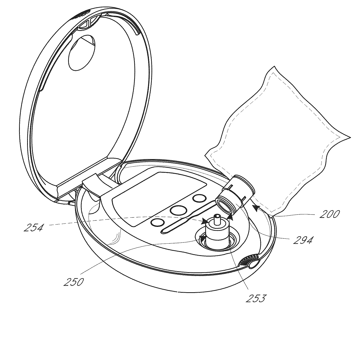
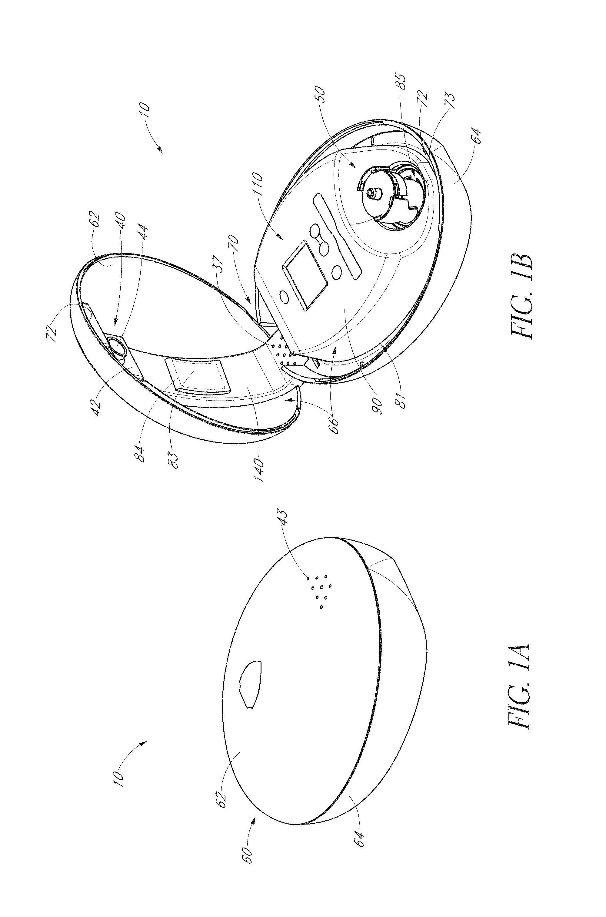
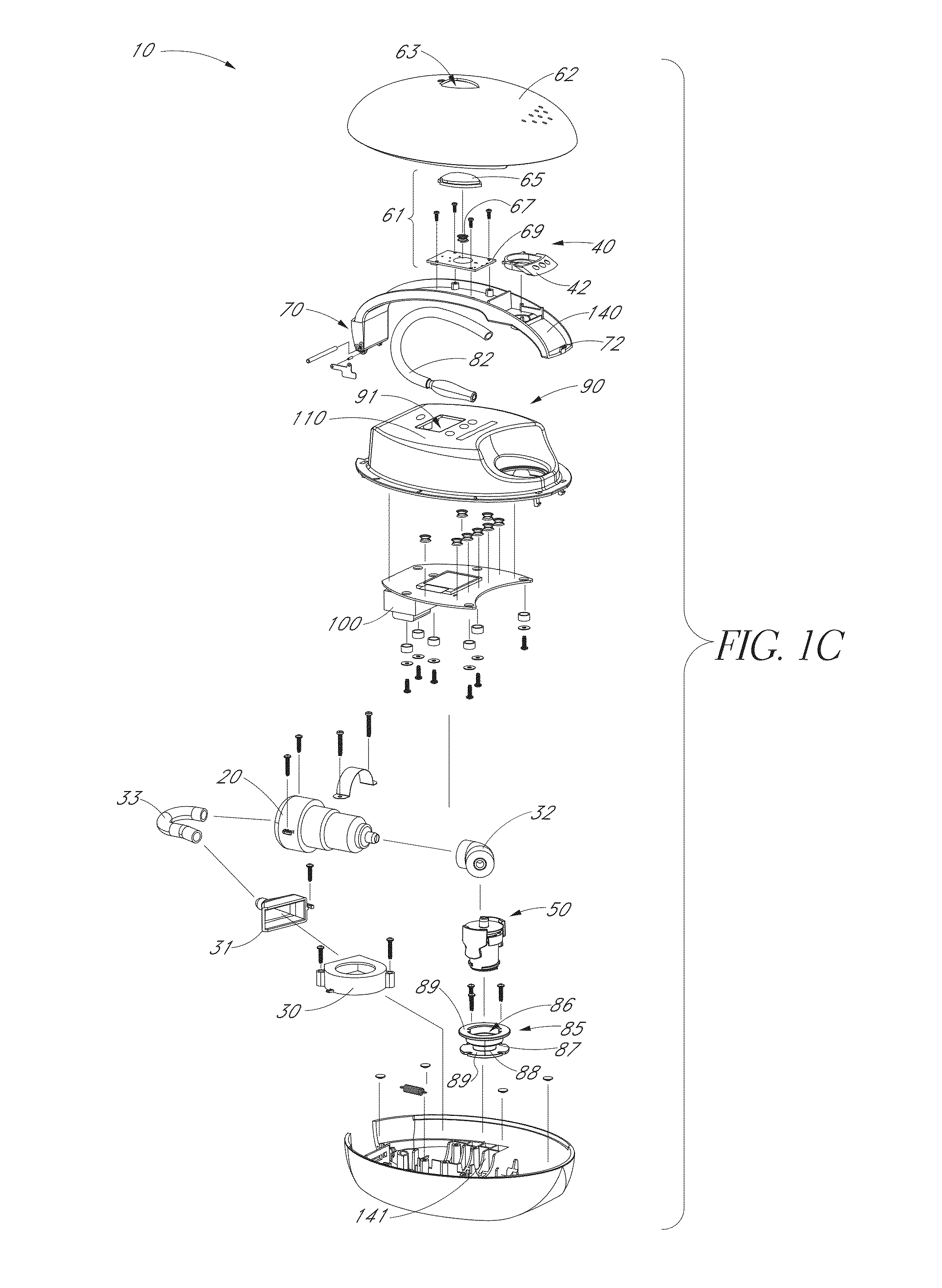
[0066]As mentioned above, conventional vaporizers are unsightly, large, cumbersome, inefficient, expensive, and difficult to use. Conventional vaporizers also include bulky accessories attached to the he...


PUM


Abstract

A therapeutic vaporizer inhalation bag attachment system with an integrated valve is disclosed. The attachment system includes a body having a lumen extending between the two openings of the body, a bag coupling, and a valve positioned within the lumen. A method of using the inhalation bag attachment system is also disclosed.

Description

CROSS-REFERENCE TO RELATED APPLICATIONS[0001]This application claims priority as a non-provisional of U.S. Provisional Patent Application No. 61 / 766,603, filed Feb. 19, 2013, and is a continuation-in-part of U.S. application Ser. No. 13 / 823,918, filed Mar. 15, 2013, which is a National Phase Application based on and claiming the benefit of PCT / US2011 / 052835, filed Sep. 22, 2011, which claims the benefit of U.S. Provisional Patent Application 61 / 385,403, filed Sep. 22, 2010, the disclosures of which are incorporated herein by reference in their entireties.BACKGROUND OF THE INVENTION[0002]1. Field[0003]The present disclosure relates generally to an apparatus for vaporizing a therapeutic material. More specifically, the present disclosure relates to a therapeutic vaporizer inhalation bag attachment system with an integrated valve.[0004]2. Description of the Related Art[0005]Many vaporizer devices are known, and are often used as a therapeutic device to provide gaseous, vaporized medica...

Claims


Application Information

Patent Timeline
Patent Type & Authority Applications(United States)
IPC IPC(8): A61M16/00A61M16/20A61M16/10A61M16/14
CPCA61M11/02A61M16/0816A61M16/20A61M2016/102A61M2202/0233A61M2205/07A61M2205/3331A61M2205/3368A61M2205/3633A61M2205/3653A61M2205/502A61M2205/583A61M2205/587A61M2205/8206A61M11/003A61M11/042A61M16/108A61M15/08A61M2209/06A61M2209/08A61M15/0021A61M16/107A61M16/0078A61M16/14
Inventor PRATT, JR., ROBERT IRVINGYOUNG, JOSHUA SMITH
Owner PRATT ROBERT IRVING JR
Why Eureka
Try Eureka