Control device for a hydraulic drive

a control device and hydraulic drive technology, applied in the direction of servomotors, elevators, fluid-pressure actuators, etc., can solve the problems of affecting the operation of the hydraulic drive, the output speed and force is no longer reliable, and the viscosity of the working fluid changes, so as to reduce the control cost and ensure the effect of stability over the expected useful li

Active Publication Date: 2014-06-12
BISIG ROLAND +1
View PDF7 Cites 10 Cited by
  • Summary
  • Abstract
  • Description
  • Claims
  • Application Information

AI Technical Summary

Benefits of technology

[0017]The coupling means, the first, and second pilot valve, and the electric actuating means are arranged as components of the pilot control means, or rather, servo control in the control device, wherein the coupling means comprises the movably supported coupling region. In its structural implementation, the coupling means, which can also be referred to as a coupling body, is mainly determined by the particular effective direction of the movements to be coupled and has in this respect to ensure, in addition to a sufficient mechanical stability over the expected useful life, essentially a defined temporary interaction via its coupling region with the two pilot valves to be coupled. This coupling region may be comprised in different coupling means made of different materials and having different surface properties. In either case, the coupling region is in relation to the two pilot valves movably arranged in such a way that an actuation of the first pilot valve from the close-position to the open-position—or vice versa—is transmittable through the coupling region to the second pilot valve so that the actuation of the latter between the close-position and the open-position can be synchronized with a corresponding actuation of the first pilot valve. The electric actuating means is configured for direct co-operation with said first pilot valve.
[0018]In order to move the coupling region of the coupling means from its first position to its second position in which the two pilot valves are no longer coupled, and thus the electric actuating means only can actuate the first pilot valve, an impact momentum is required which is applied by an impulse generating means. As such, in principle all actuating means are eligible which are capable to provide the mechanical energy necessary for the change of position as kinetic energy, such as a spring or an electromagnetic transducer. Irrespective of the type of impulse generating means ultimately used, in any case an impulse guiding means for defined alignment, or rather, guiding of the impact momentum on the coupling means generated by the impulse generating means is provided. This impulse guiding means has a first and a second end and is configured so that an impact momentum generated by the impulse generating means is largely lossless guidable from the first via the second end to the coupling means. Such a suitable impulse guiding means is insofar, for example, a hydraulic conduit means with its inlet and its outlet provided in the form of a tube supplying a fluid as impulse generating means and, therefore, a pressure pulse conveyed by it as an impact momentum to the coupling means in such a way that the increase of pressure in the fluid at the outlet of the tube, i.e. at the second end of the impulse guiding means, enables a desired displacement of the coupling region of the coupling means. Generally, the impulse guiding means is always adapted to the impulse generating means in such a way that an impact momentum generated by the impulse generating means ensures a reliable release of the coupling region of the coupling means from each pilot valve and a defined movement of the coupling region of the coupling means from its first to its second position.
[0019]In addition to a direct transmission of the impact momentum with the impulse generating means guided by the impulse guiding means directly acting on the coupling means, also an indirect or mediated impact momentum transmission between the impulse generating means and the coupling region of the coupling means from the first via the second end of the impulse guiding means can be advantageous from case to case. As impulse transmission means, preferably movably guided rigid bodies, or rather, plungers are used, but without basically ruling out other means of transmission, such as fluids. The impulse guiding means also is adapted in a suitable manner to the particular impulse transmission means so that this alternative embodiment of the invention ensures a reliable releasing of the coupling region of the coupling means from each pilot valve and its defined movement from the first to the second position too. As plunger material may be used any material suitable for hydraulic applications which has the necessary mechanical rigidity. Preferably, the plunger is made of metal, such as steel.
[0020]This alternative embodiment is particularly advantageous, when use is made of commercially available components in the realization of the displacement function. Such transmission means comprise in a structural unit usually, in addition to a standardized connector for the impulse generating means, a mostly one-part plunger movable

Problems solved by technology

With strongly varying loads acting on the hydraulic consumer, however, as is the case in a hydraulic drive system for an elevator, fluctuations with regard to pressure and output movement may occur owing to the elasticity of volume of the working fluid, whereby the desired consistency of the output movement, or rather, output speed and force no longer is reliable.
By strong operational heating of the working fluid, changes in viscosity in the working fluid may occur in addition, having similar adverse effects on the operating characteristics of the hydraulic drive system.
In particular, the desired continuity of the output movement of the hydraulic consumer may also be adversely affected by pump-induced fluctuations of the volume flow of the working fluid.
Nonetheless, the l

Method used


Image

  • Control device for a hydraulic drive
  • Control device for a hydraulic drive
  • Control device for a hydraulic drive

Examples


Embodiment Construction

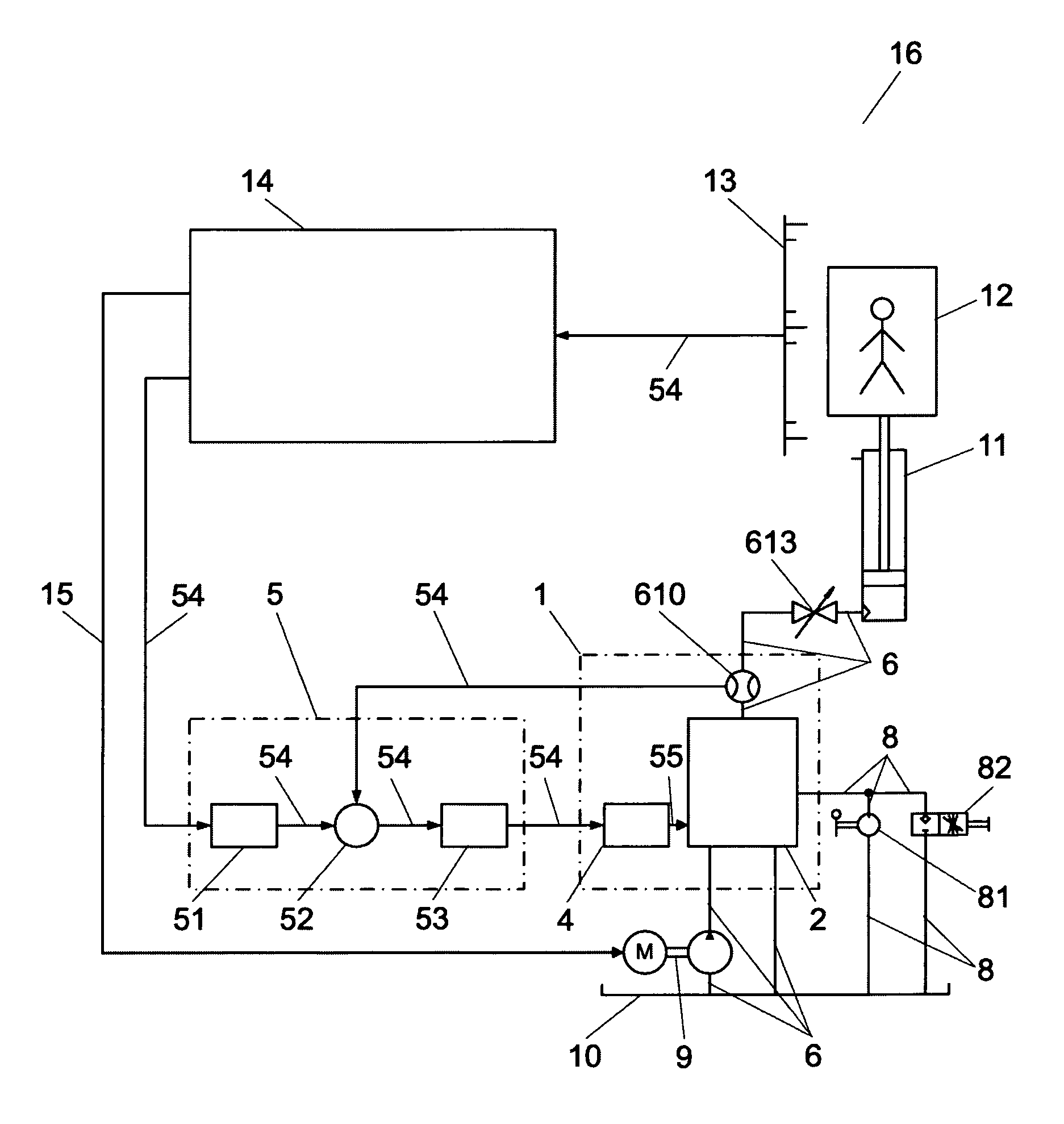
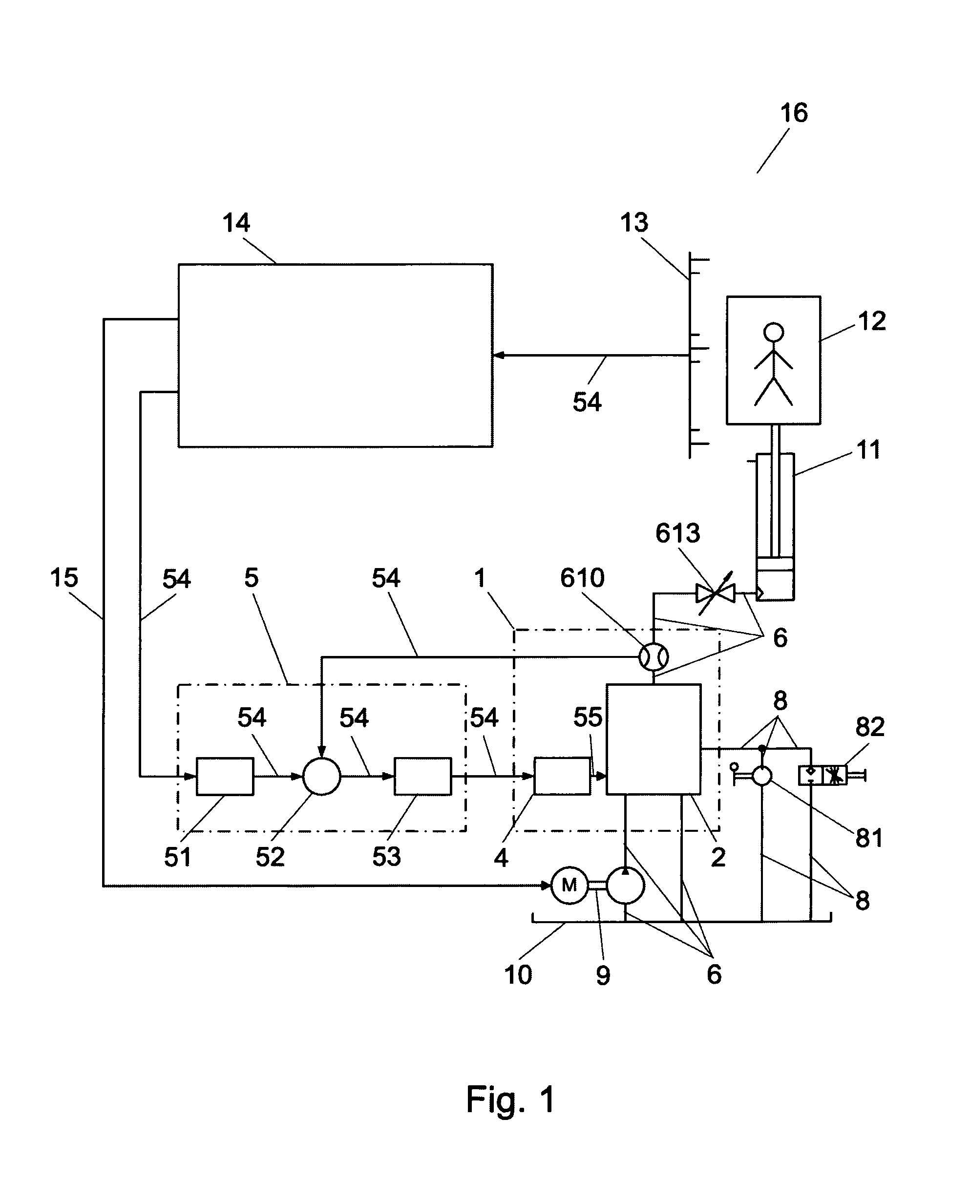
[0055]The preferred embodiment of the invention illustrated in the drawings sets forth the best mode for carrying out the invention. This best mode embodiment of the present invention will be described in detail below. In FIG. 1 the electro-hydraulic circuit diagram of a hydraulic drive system 16 for an elevator is shown in which the inventive control device 1 carries out controlling and timing of the lifting and lowering motion. Hydraulic elevator systems of this kind are used in buildings with several floors, especially in buildings with up to six floors, and have a movable elevator car 12 suitable for transportation of passengers and / or goods. As further components the hydraulic drive system 16 comprises a control device 1 with a valve block 2 which is connected via a flow path 6 in the form of a hydraulic power conduit usually provided as a pipe joint with a hydraulic cylinder 11 as a hydraulic drive. The hydraulic cylinder 11 is configured as a single-stage drive cylinder and c...


PUM


Abstract

The invention relates to a control device (1) for a working fluid for operating a hydraulic drive (11) such as is used, in particular, for an elevator. Said control device (1) comprises a flow path (6) for directing a volume flow of the working fluid in a first and second direction, a first and second control valve (21, 22) for controlling the volume flow, a flow-measuring means (610) for detecting the volume flow, a pilot control means (3) with a first and second pilot valve (31, 32), and an electric actuating means (4) for interacting with a comparing means (52) for comparing the detected volume flow with a volume flow reference value which can be predefined by a reference value-setting means (51), and a controller (53) for generating an actuating signal for activating the first and second pilot valve (31, 32) via a coupling means (33) which can move to and fro between a first and second position for controlling the volume flow of the working fluid through the first and second control valve (21, 22), wherein in the first position of the coupling means (33) each pilot valve (31, 32) can be actuated and in the second position of the coupling means (33) only the first pilot valve (31) can be actuated by the electric actuating means (4). Furthermore, the invention relates to a hydraulic drive system (16) for an elevator having the control device (1) and to a method for retrofitting such a drive system. The invention is distinguished from conventional control devices in addition to simplifications in the design and operation and corresponding cost advantages as well, in particular, by a relatively low degree of expenditure on maintenance accompanied at the same time by an increased reliability. Said invention permits in a hydraulic drive system the automatic compensation of drive-side and output-side interference variables as well as load-induced fluctuations in the working fluid pressure in favor of a continuous output movement and load-independent starting without a delay, consequently an overall improvement in the starting quality in an elevator.

Description

FIELD OF THE INVENTION[0001]The invention relates to a control device for a hydraulic drive, or rather, for a working fluid of a hydraulic drive, such as is particularly used in hydraulic drive systems for elevators, and enables control of the working fluid with regard to direction and volume in accordance with a presettable volume flow reference value. Furthermore, the invention relates to a hydraulic drive system for an elevator and a method for retrofitting such a drive with the control device according to the invention.BACKGROUND OF THE INVENTION[0002]In hydraulic drives, the driving power is known to be controlled by the pressure and the flow velocity of a working fluid conducted in a circuit from a reservoir, usually formed as an oil pan, via the pressure side of a motor-driven pump to a hydraulic consumer and from the low-pressure side of the latter back to the reservoir. To conduct the working fluid in this cycle, hydraulic power conduits are provided in flow connection betw...

Claims


Application Information

Patent Timeline
IPC IPC(8): B66B1/30B66B9/04
CPCB66B1/24F15B11/0423F15B11/044F15B2211/30505F15B2211/30565F15B2211/31511F15B2211/31558F15B2211/329F15B2211/6326F15B2211/6654F15B2211/7052F15B2211/761B66B1/30B66B9/04
Inventor BISIG, ROLANDIBRISIMBEGOVIC, ESAD
Owner BISIG ROLAND
Why Eureka
Try Eureka