Disk brake with a parking brake, mechanical thrust assembly, and method of assembling

Active Publication Date: 2014-06-12
CHASSIS BRAKES INT BV
View PDF7 Cites 32 Cited by
  • Summary
  • Abstract
  • Description
  • Claims
  • Application Information

AI Technical Summary

Problems solved by technology

Mounting difficulties, or even impossibilities, result when the transverse face of the rear extremity of the rear section of the screw comes into abutment against a portion facing the bottom of the cavity, and, for example, against the machined internal face of the bottom wall, or possibly even against the annular seal.

Method used


Image

  • Disk brake with a parking brake, mechanical thrust assembly, and method of assembling
  • Disk brake with a parking brake, mechanical thrust assembly, and method of assembling
  • Disk brake with a parking brake, mechanical thrust assembly, and method of assembling

Examples


Embodiment Construction

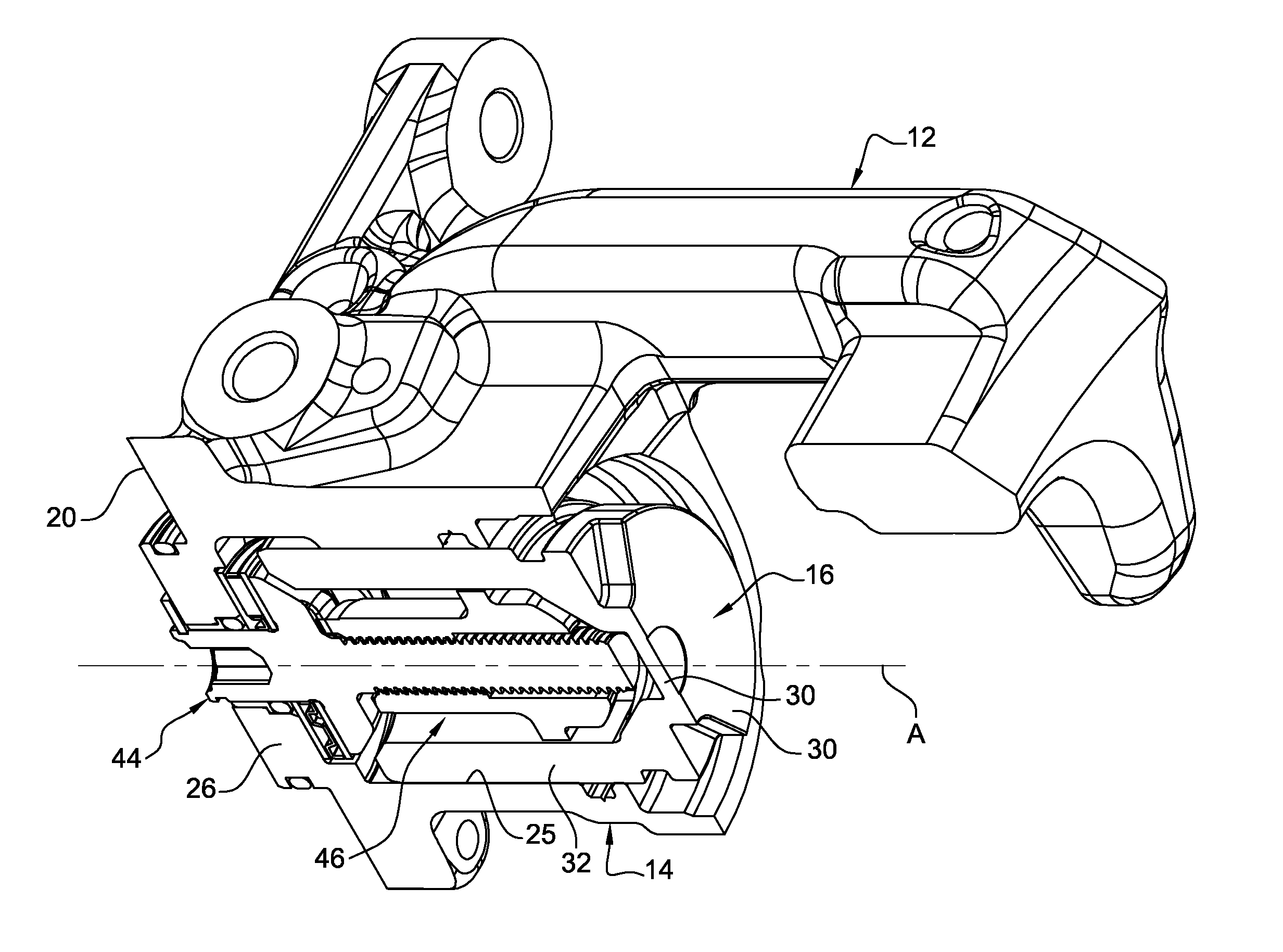
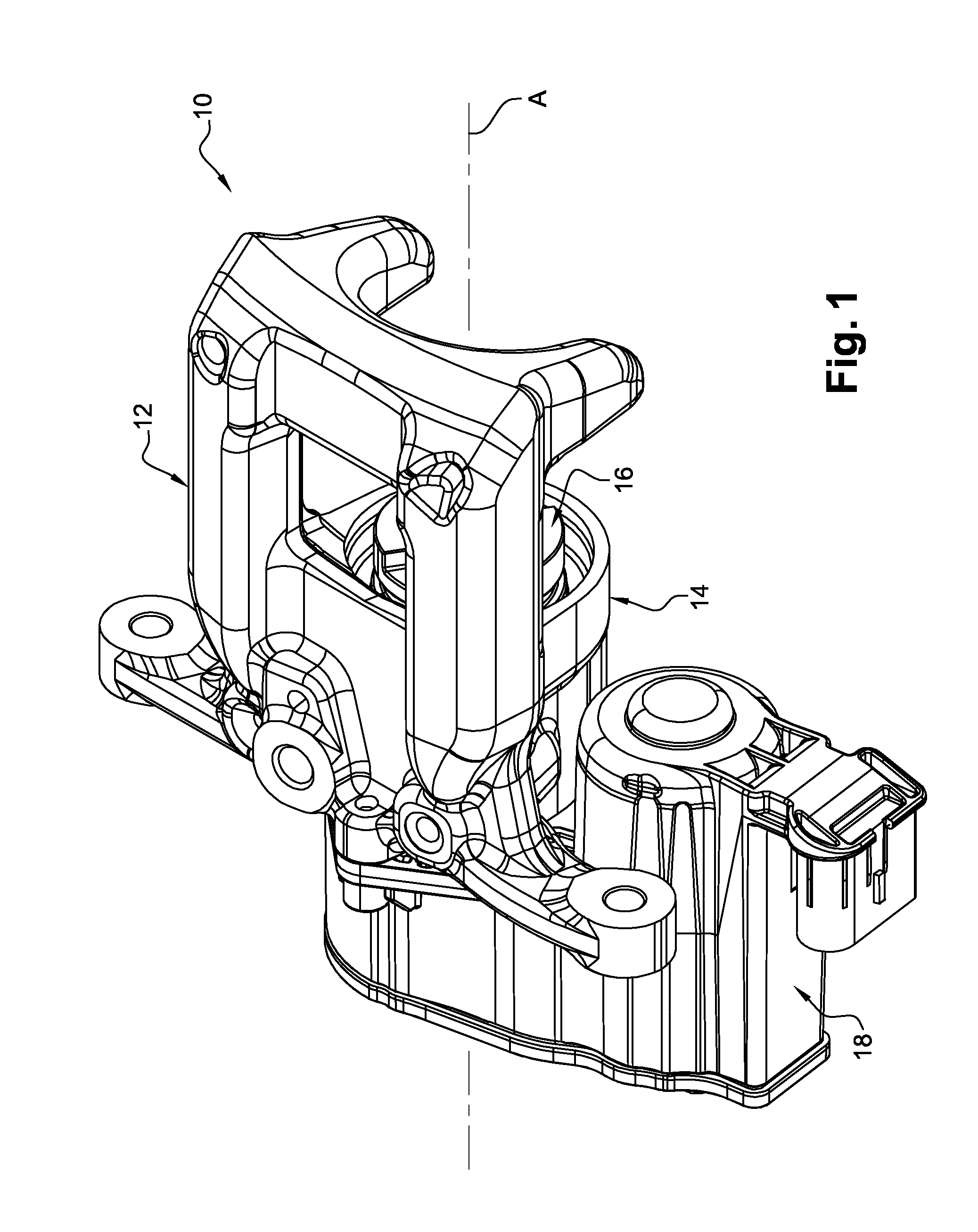
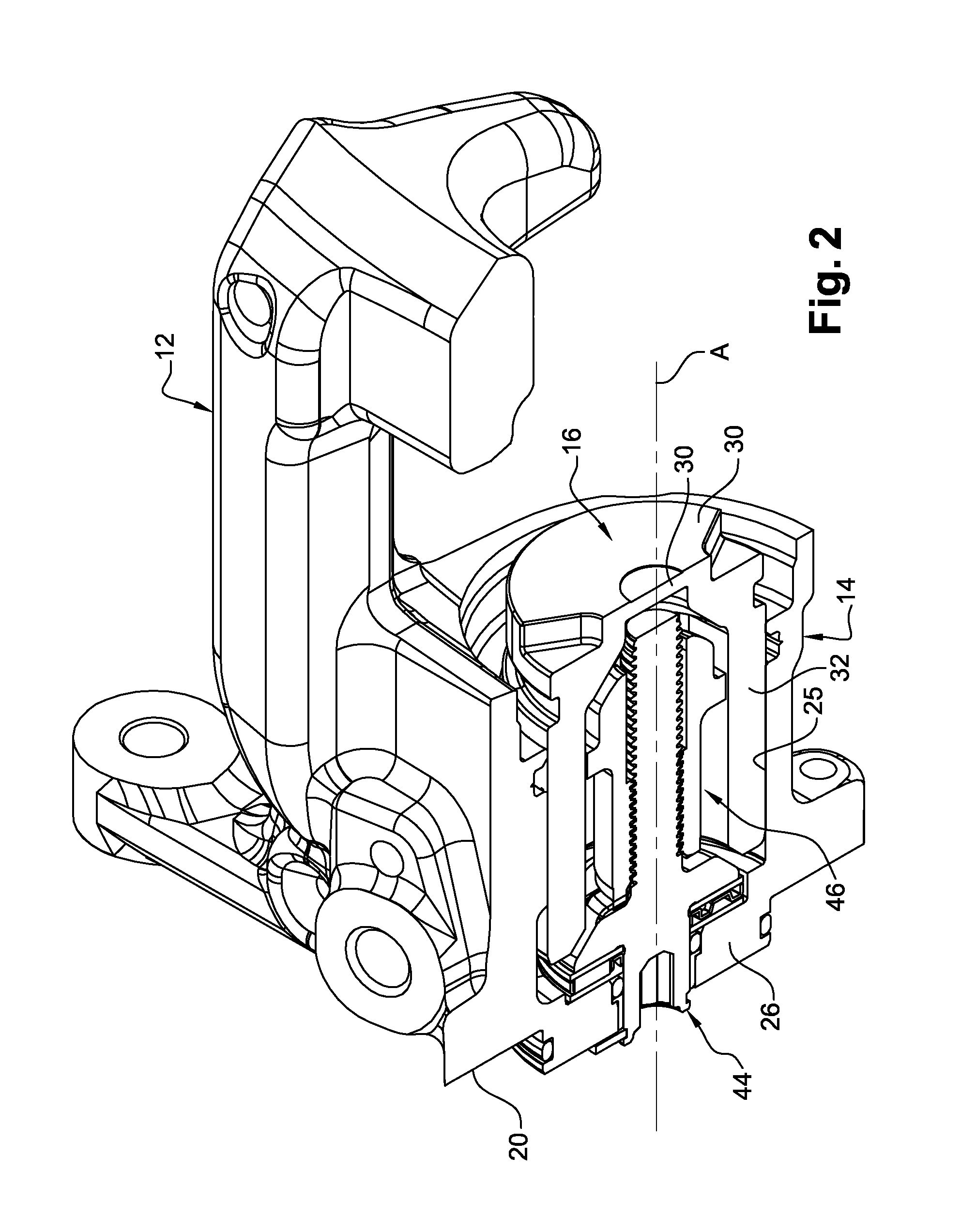
[0024]To this end, the invention proposes an arrangement containing:[0025]a brake piston, for the operation of at least one disk brake pad that contains a front transverse wall having a radial orientation and a lateral cylindrical tubular wall that extends axially towards the rear; and[0026]a nut-and-screw unit for the axial thrusting of the piston, from the rear to the front, that contains:[0027]a nut that is arranged in the interior of the piston, in relation to which it is secured in order to prevent rotation, and in which it is mounted so as to slide axially, the front axial end face of which interacts with an internal section facing the front wall of the piston in order to push the piston axially towards the front when the screw is driven in a rotating manner in the direction of unscrewing;[0028]a screw containing a front section that is mounted screwed into the nut, an intermediate radial axial abutment flange delimited by a rear transverse face, and a rear section,

characteriz...


PUM


Abstract

An arrangement contains a brake piston for operating at least one disk brake pad and a nut-and-screw unit for producing an axial thrust, from the rear to the front, of the piston containing a nut arranged in the piston's interior, and secured thereto to prevent rotation, and mounted therein to slide axially, whose front axial end face interacts with an internal section facing the piston's front wall to push the piston axially towards the front when the screw is rotatably driven in the unscrewing direction, and the screw containing a front section screwed into the nut, an intermediate radial flange and a rear section, wherein the piston screw contain centering elements that interact with one another when the screw is in a predetermined front axial mounting position in relation to the piston in order to center the rear section of the screw radially in relation to the piston.

Description

TECHNICAL FIELD OF THE INVENTION[0001]The present invention relates to a hydraulically operated disk brake intended for a motor vehicle and containing an electromechanically operated parking brake, or brake for “parking”.[0002]The invention relates in particular to an arrangement containing a hydraulic brake piston for the operation of at least one disk brake pad and a nut-and-screw unit for the mechanical axial thrusting of this piston.[0003]The invention further relates to a method of mounting such an arrangement in a disk brake caliper.DESCRIPTION OF THE PRIOR ART[0004]The general construction of a hydraulically controlled disk brake containing an electromechanical parking brake is already familiar, in particular from documents EP-B1-2.174.037 or U.S. Pat. No. 7,721,853.[0005]In a known manner, the brake contains a caliper that is capable of supporting and guiding two opposing sliding friction pads that are capable of interacting with a rotating disk.[0006]The caliper contains a ...

Claims


Application Information

Patent Timeline
Patent Type & Authority Applications(United States)
IPC IPC(8): B60T11/10B60T11/04B60T1/06
CPCB60T11/102B60T11/04B60T1/065F16D55/226F16D2121/04F16D2121/24F16D2123/00F16D2125/06F16D2125/40F16D2250/0084F16D65/183
Inventor QIAN, NANBOURLON, PHILIPPE
Owner CHASSIS BRAKES INT BV
Why Eureka
Try Eureka