Variable venting and damping arc mitigation assemblies and methods of assembly

Active Publication Date: 2014-06-12
ABB (SCHWEIZ) AG
View PDF6 Cites 14 Cited by
  • Summary
  • Abstract
  • Description
  • Claims
  • Application Information

AI Technical Summary

Problems solved by technology

However, if the conductors are positioned too closely together, or if a voltage between the conductors exceeds the dielectic strength of the insulation between the conductors, an arc flash can occur.
Arc flash also can occur in case of aging insulations, rodents, and improper maintenance procedures.
In addition, an arc fault is associated with release significant amount of energy in the form of heat, intense light, pressure waves, and/or sound waves due to which heavy dam

Method used


Image

  • Variable venting and damping arc mitigation assemblies and methods of assembly
  • Variable venting and damping arc mitigation assemblies and methods of assembly
  • Variable venting and damping arc mitigation assemblies and methods of assembly

Examples


Embodiment Construction

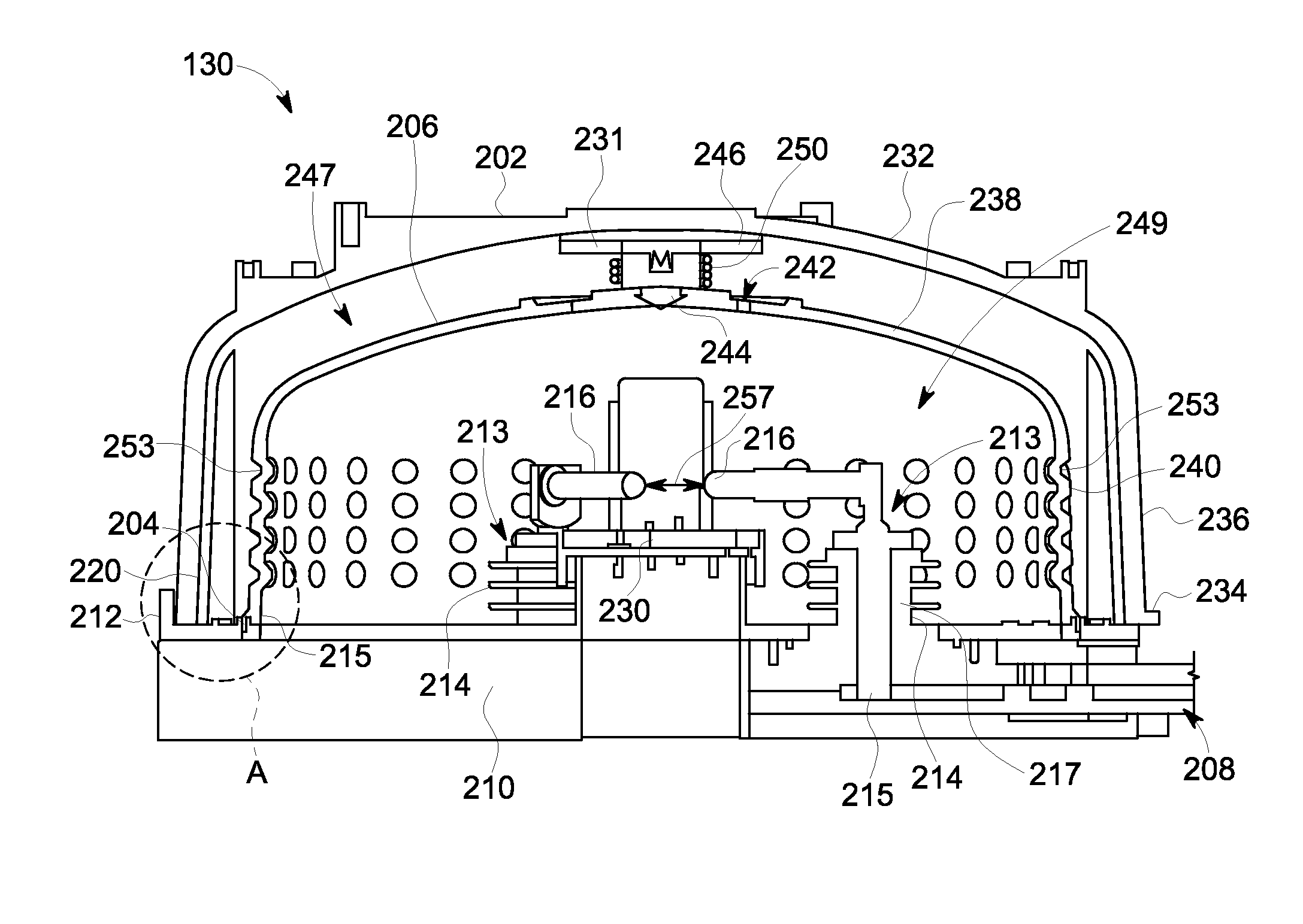
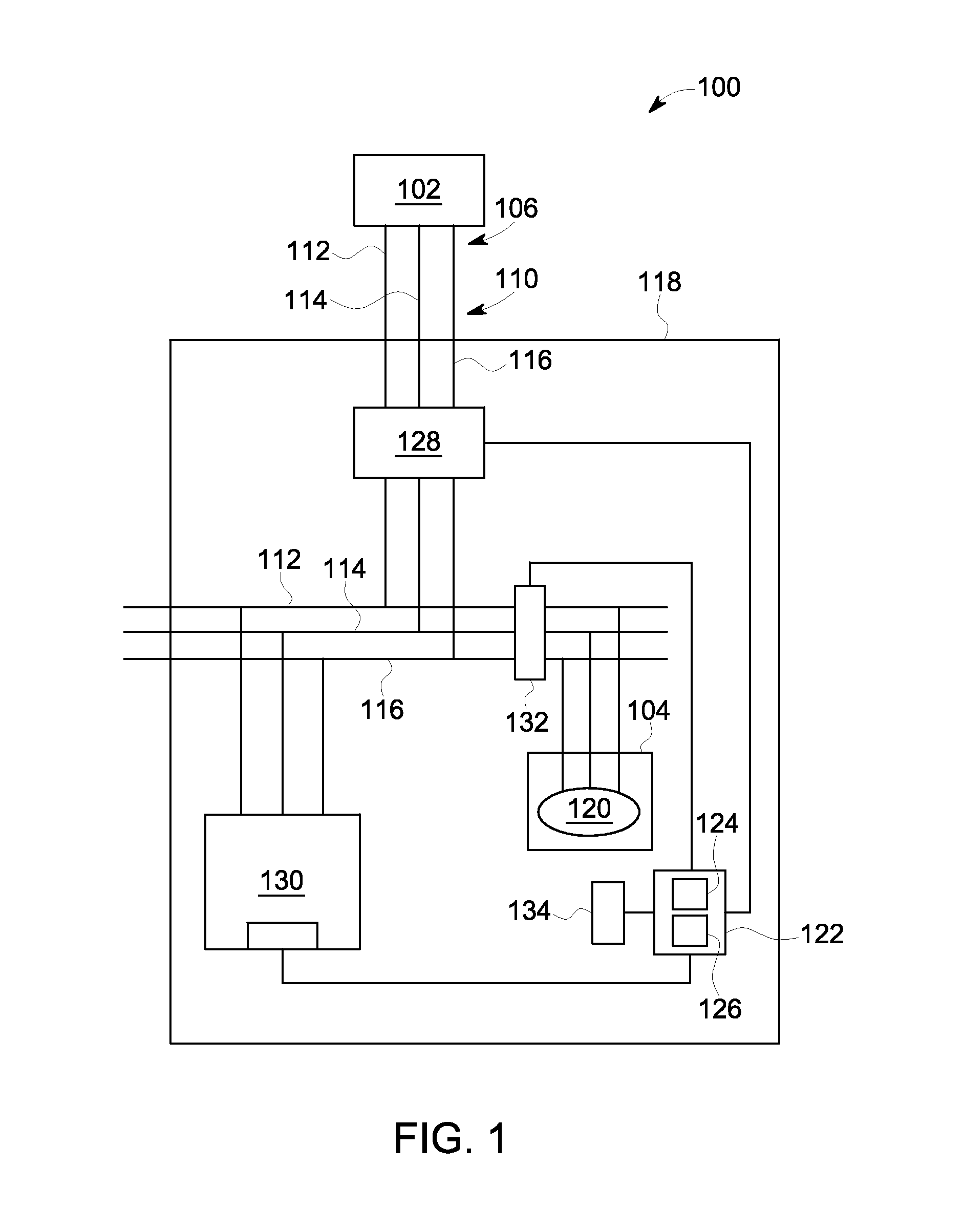
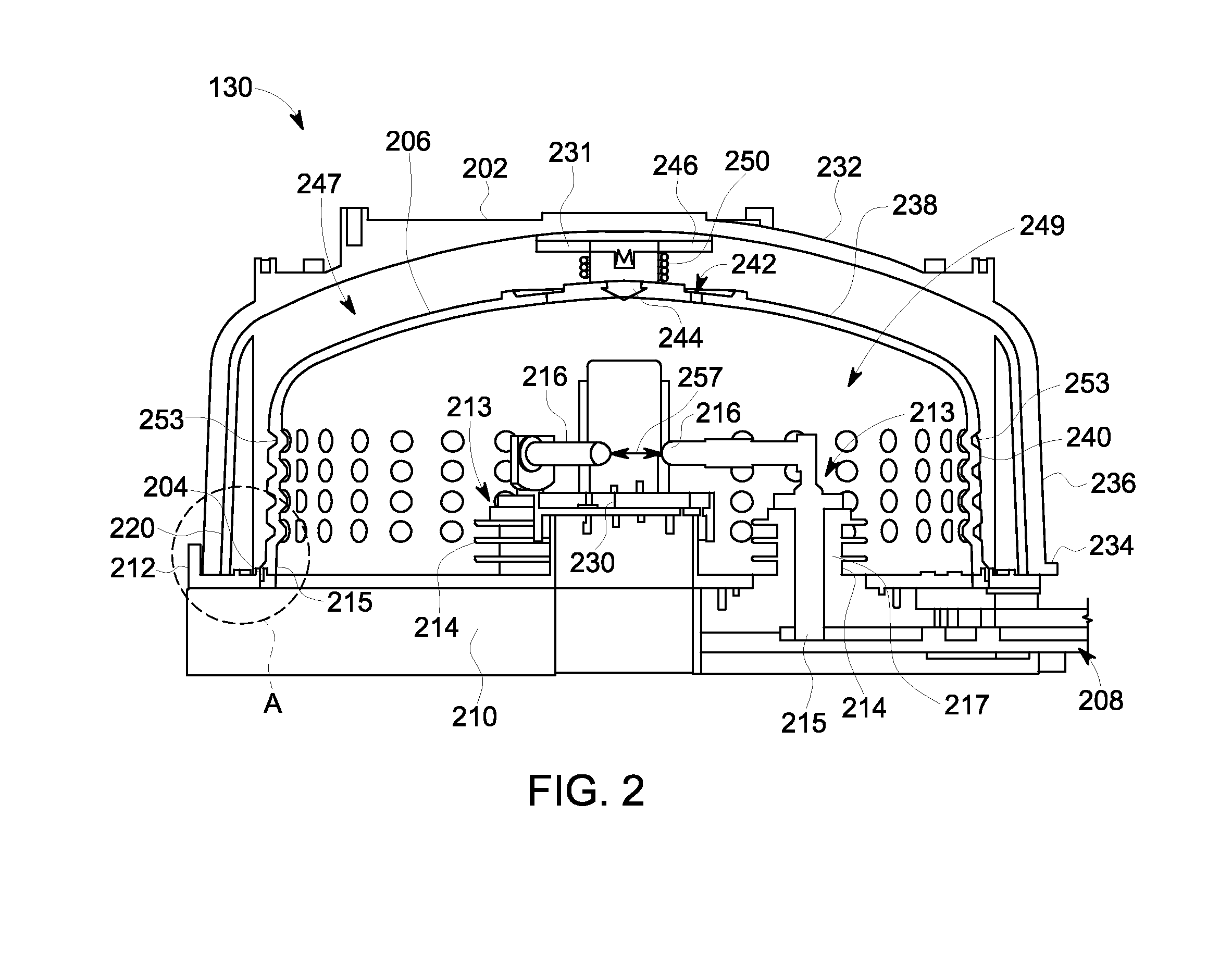
[0014]Exemplary embodiments of systems and apparatus for use with a circuit protection are described herein. More particularly exemplary embodiments of systems and apparatus for use in arc mitigation systems are described. These embodiments enhance the flow of ionized gases, heat, metal shrapnel, and pressure out of the circuit protection system after an arc flash is generated. For example, the arc protection system can receive a signal that indicates detection of a primary arc flash within a power system being monitored by the arc protection system. The arc protection system can then generate a secondary arc flash to transfer the energy from the primary arc flash to the arc mitigation system or containment device. Moreover, these embodiments enhance, as appropriate to the rating of the device, the flow of exhaust gases, heat, metal shrapnel, and pressure created by the secondary arc out of an arc containment chamber to the equipment enclosure that contains the arc containment syste...


PUM

PropertyMeasurementUnit
Lengthaaaaaaaaaa
Forceaaaaaaaaaa
Pressureaaaaaaaaaa

Abstract

Equipment protection systems, arc containment devices, and methods of assembling arc containment devices are disclosed. In one example, an electrical isolation structure includes a conductor base, a cover coupled to the conductor base and defining an isolation chamber, a containment shield disposed on the conductor base within the isolation chamber, and a biasing assembly positioned between the cover and the containment shield. The containment shield defines a containment chamber configured to enclose the plurality of electrode assemblies. The containment shield is configured to at least partially contain the arc products within the containment chamber. The biasing assembly is configured to permit the containment shield to move away from the conductor base to thereby define a gap between the conductor base and the containment shield to enable at least some of the arc gases to vent from the containment chamber.

Description

BACKGROUND[0001]The embodiments described herein relate generally to power equipment protection devices and, more particularly, to arc mitigation systems for use in channeling exhaust gases and pressure away from a location of arc generation.[0002]Known electric power circuits and switchgear generally have conductors that are separated by a distance with insulation, such as air, or gas or solid dielectrics. However, if the conductors are positioned too closely together, or if a voltage between the conductors exceeds the dielectic strength of the insulation between the conductors, an arc flash can occur. Arc flash also can occur in case of aging insulations, rodents, and improper maintenance procedures. The insulation between the conductors can become ionized, which makes the insulation conductive and enables arc formation. An arc flash causes rapid release of energy due to a fault between phase conductors, between a phase conductor and a neutral conductor, or between a phase conduct...

Claims


Application Information

Patent Timeline
IPC IPC(8): H02H1/00H01H69/00
CPCH01H69/00H02H1/0015H01H9/50H01T1/15H01T2/02Y10T29/49117H01T4/04
Inventor PALVADI, SRINIVAS NAGAKUMAR, RAVIGOPULARAM, CHANDRAKANTH
Owner ABB (SCHWEIZ) AG
Why Eureka
Try Eureka