Sonar system and impedance matching method thereof

a sonar system and impedance matching technology, applied in the direction of seismic energy generation, mechanical vibration separation, instruments, etc., can solve the problems of low output impedance of methods that are not so useful to be applied to the active sonar system, and limited maximum efficiency of the conventional impedance matching method up to 50%, etc., to achieve the enhancement of output power performance and detection performance, the physical size of the matching circuit components may be minimized, and the effect of increasing the power factor

Active Publication Date: 2014-06-12
AGENCY FOR DEFENSE DEV
View PDF18 Cites 13 Cited by
  • Summary
  • Abstract
  • Description
  • Claims
  • Application Information

AI Technical Summary

Benefits of technology

[0019]In accordance with the detailed description, an impedance matching circuit which is minimized a reactance component of transducer and increased its power factor may allow the efficient driving in a broadband between a transmitter and a transducer in an active SONAR system, and have effects which are greatly contributing to enhancement of output power performance and detection performance of the active SONAR system.
[0020]From the perspective of design factors of an electrical driving unit, such as driving characteristic, protection against heat, power capacity, transmitting acoustic pressure level and the like, there are the effects that a driving voltage control and leakage current minimization of the transducer may be allowed, and the physical size of matching circuit components may be minimized by using a turn ratio of a transformer. Also, a fabrication of unnecessary real hardware can be minimized and fabrication costs and time can be reduced when active sonar devices are produced.

Problems solved by technology

However, most of conventional impedance matching methods are subject to a limitation of maximum efficiency up to 50% due to performing a conjugate impedance matching for transmission of maximum power to the load.
Especially, these methods are not so useful to be applied to the active sonar system, which exhibits very low output impedance of its transmitter and operates within a limited range of supplied power.
However, an electrical characteristic of the transducer matched by such method exhibits large deviations for an input impedance and supplied power even within the matched frequency range.
Also, the deviations depend on physical characteristics of the transducer, that the control by the matching method is difficult.
However, the physically fixed parameters of the transducer cause a constraint to an impedance matching bandwidth for minimizing a reactance component, required for high efficiency operation.

Method used


Image

  • Sonar system and impedance matching method thereof
  • Sonar system and impedance matching method thereof
  • Sonar system and impedance matching method thereof

Examples


Embodiment Construction

[0030]Description will now be given in detail of the exemplary embodiments, with reference to the accompanying drawings. For the sake of brief description with reference to the drawings, the same or equivalent components will be provided with the same reference numbers, and description thereof will not be repeated.

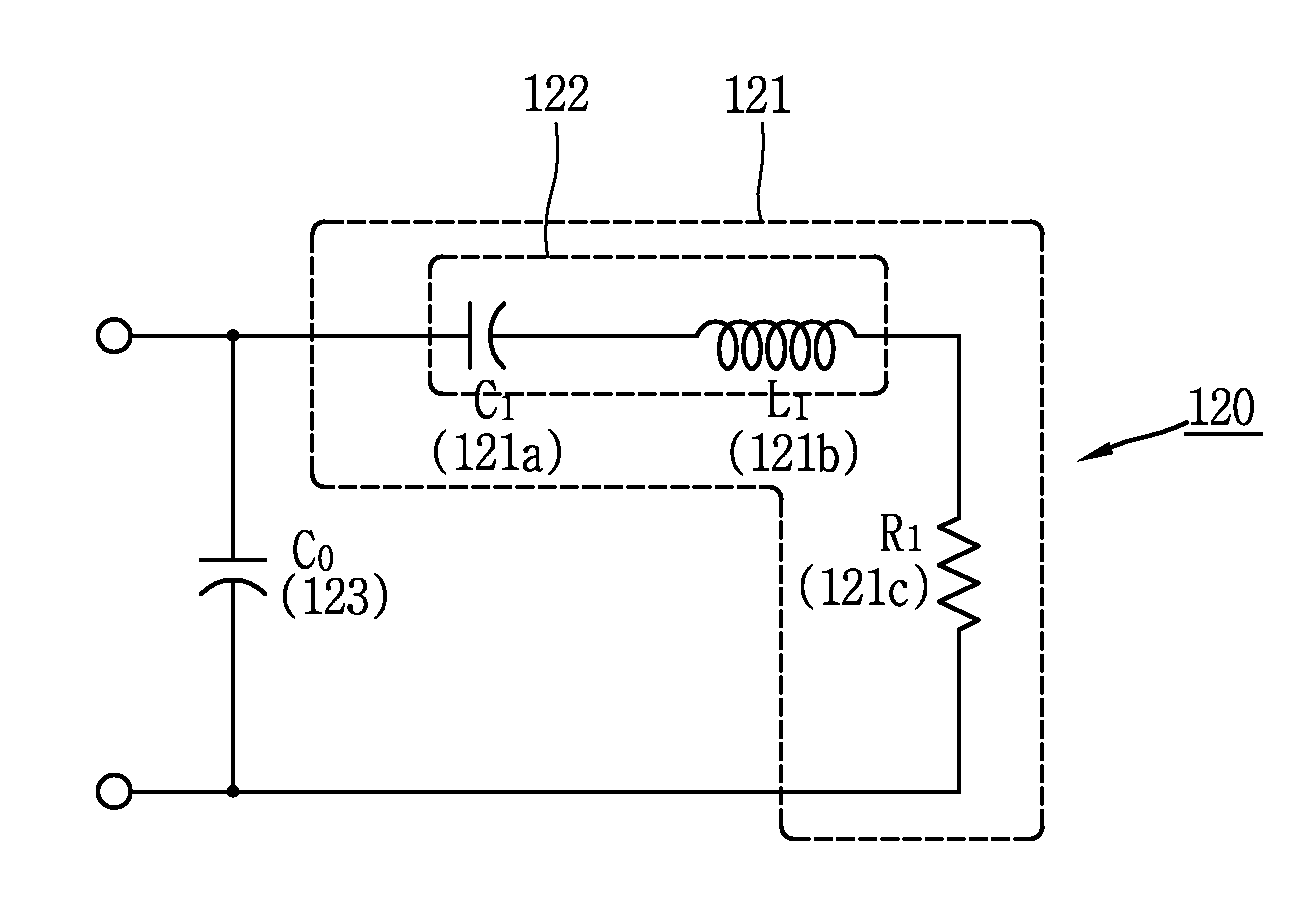
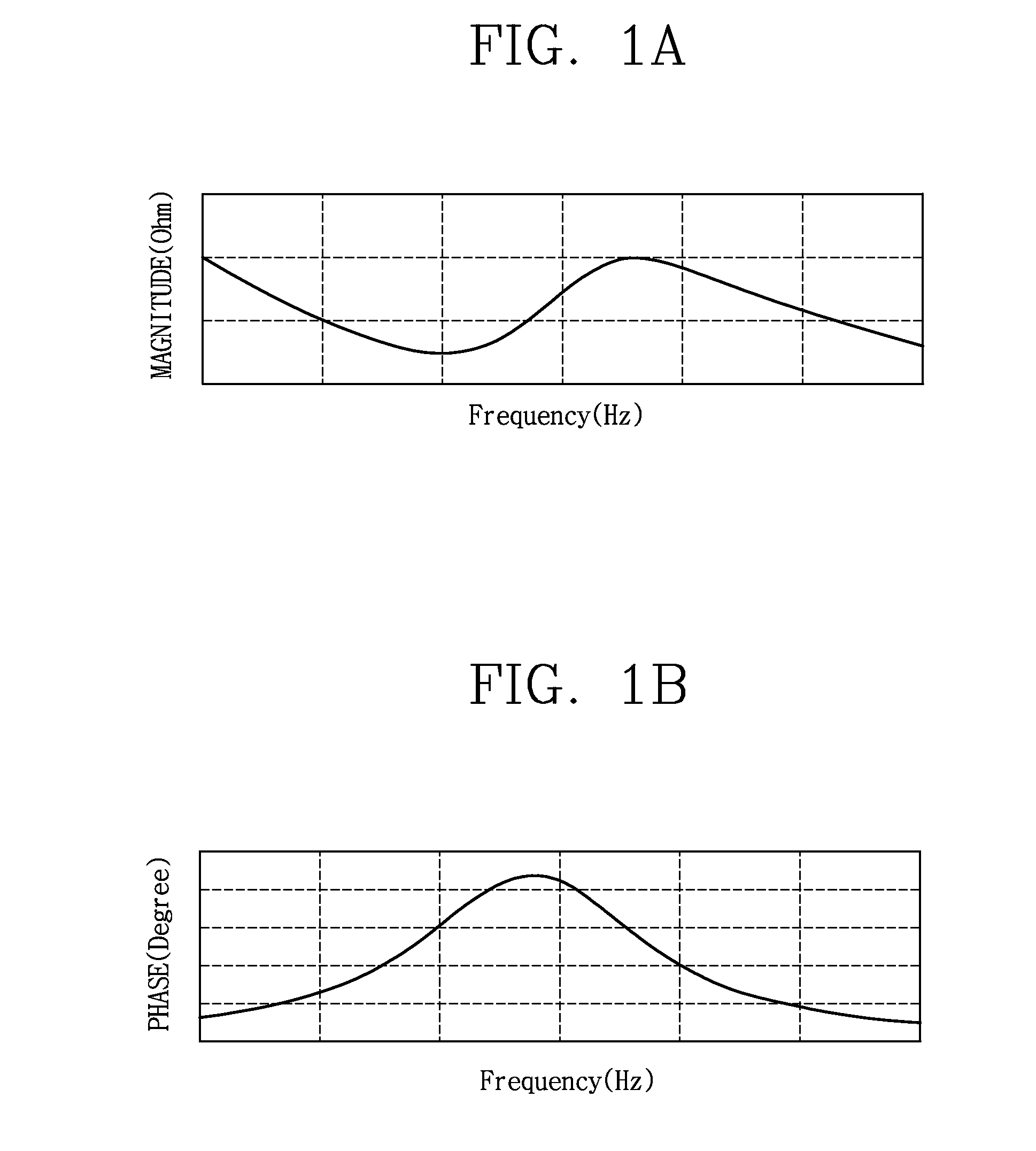
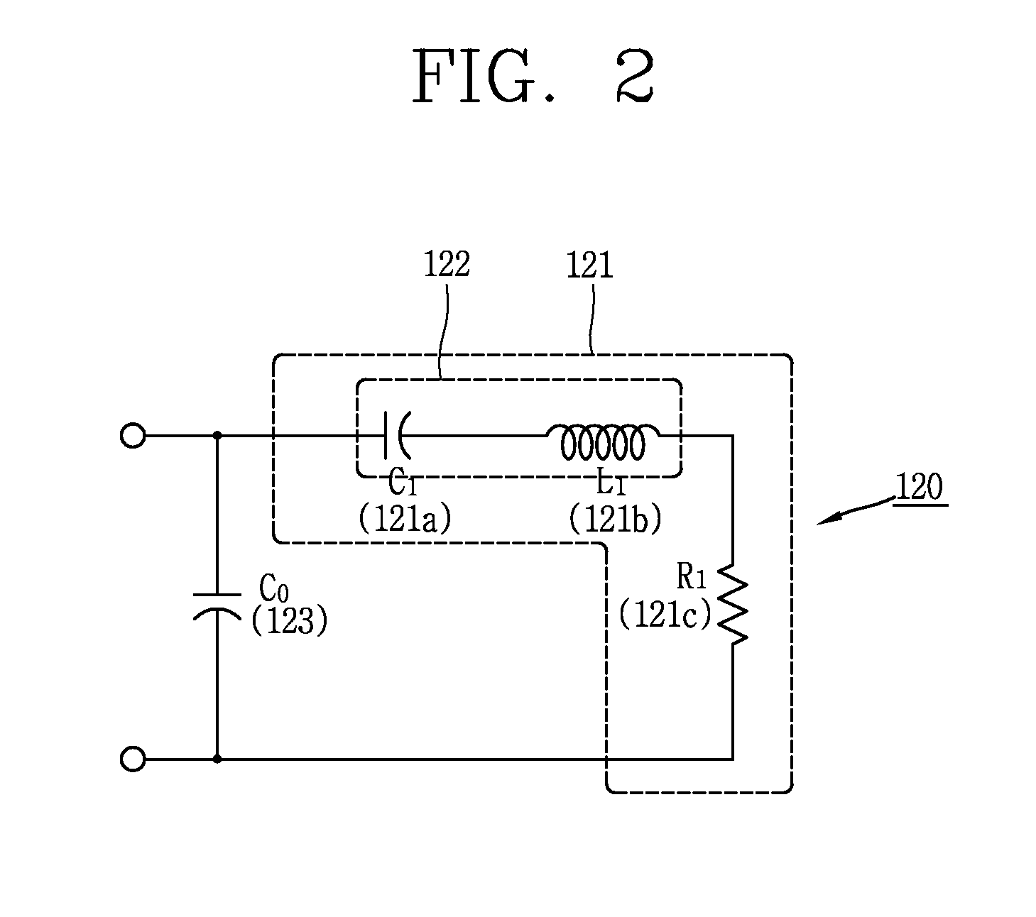
[0031]Hereinafter, description will be given in detail of an active sonar system and an impedance matching method in accordance with one exemplary embodiment. FIG. 1 illustrates impedance characteristics of a single-mode transducer 120 according to the frequencies in the acoustic and ultrasonic wave bands in accordance with the present disclosure. FIG. 1A illustrates magnitude values of the impedance according to the frequency, and FIG. 1B illustrates phase values of the impedance according to the frequency. It can be understood that resonance is generated at the frequency adjacent to a peak value of the impedance phase of FIG. 1B, the number of resonances corresponds to t...


PUM


Abstract

This specification relates to an active SONAR system comprising a transmitter, a transducer and an impedance matching circuit for expanding bandwidth and increasing a power factor value in sound and ultrasonic wave bands by mutually matching resonant frequencies of the transducer and the impedance matching circuit or a resonant frequency between the transducer and the impedance matching circuit using an electrical equivalent model corresponding to actual impedance data of the transducer and controlling the positions and the intervals of the frequencies at which reactance components of the transducer including the impedance matching circuit become zero, and an impedance matching method thereof. This allows for efficient driving in a broadband between the transmitter and the transducer in the active SONAR system, contributing to output power performance and detection performance of the active SONAR system.

Description

BACKGROUND OF THE INVENTION[0001]1. Field of the Invention[0002]This specification relates to an active Sound Navigation and Ranging (SONAR) system and an impedance matching method thereof, and particularly, to an active SONAR system having an impedance matching circuit for driving underwater acoustic transducers in broadband and with high efficiency and the impedance matching method thereof, capable of obtaining matching circuit element values by controlling the positions and the intervals of the frequencies at which reactance components of a transducer become zero.[0003]2. Background of the Invention[0004]A radar, laser or infrared rays using electric waves are used to detect a target on land or in the air, but Sound Navigation and Ranging (SONAR) using acoustic waves is used to detect a target under the water. Active SONAR is essential acoustic equipment for a ship, which allows for safe sailings and serves to find an underwater (submarine) object which poses a threat to the ship...

Claims


Application Information

Patent Timeline
Patent Type & Authority Applications(United States)
IPC IPC(8): G01S15/02
CPCG01S7/524G01V1/04B06B1/0215G01S15/02
Inventor LEE, JEONG MINLEE, BYUNG HWA
Owner AGENCY FOR DEFENSE DEV
Why Eureka
Try Eureka