Cyclone Separation Device

Active Publication Date: 2014-06-19
MANN HUMMEL GMBH
View PDF6 Cites 29 Cited by
  • Summary
  • Abstract
  • Description
  • Claims
  • Application Information

AI Technical Summary

Benefits of technology

[0005]An object of the present invention resides in that a separating device i

Problems solved by technology

Moreover, with regard to construction technology, a simplification results in t

Method used


Image

  • Cyclone Separation Device
  • Cyclone Separation Device
  • Cyclone Separation Device

Examples


Embodiment Construction

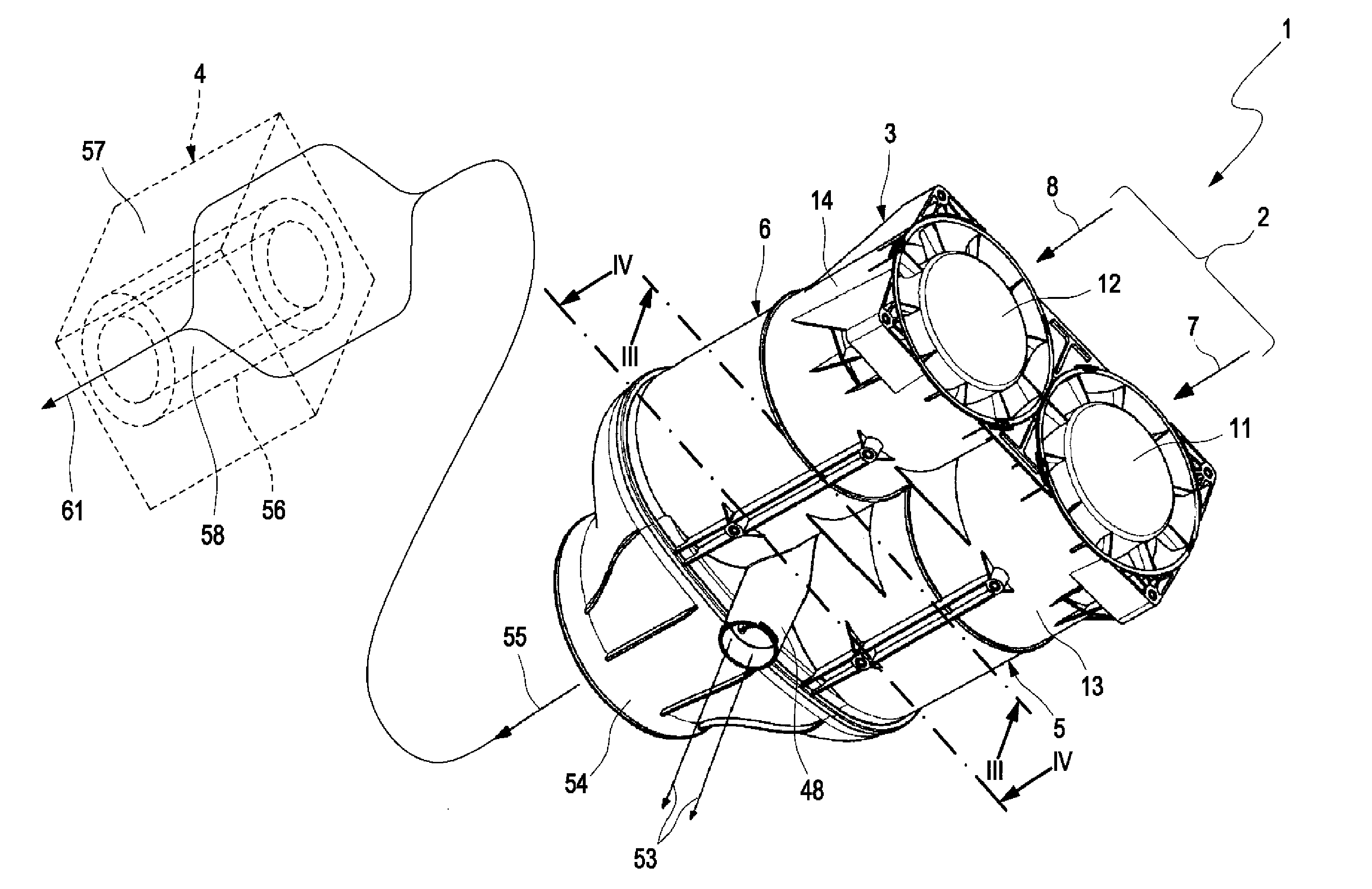
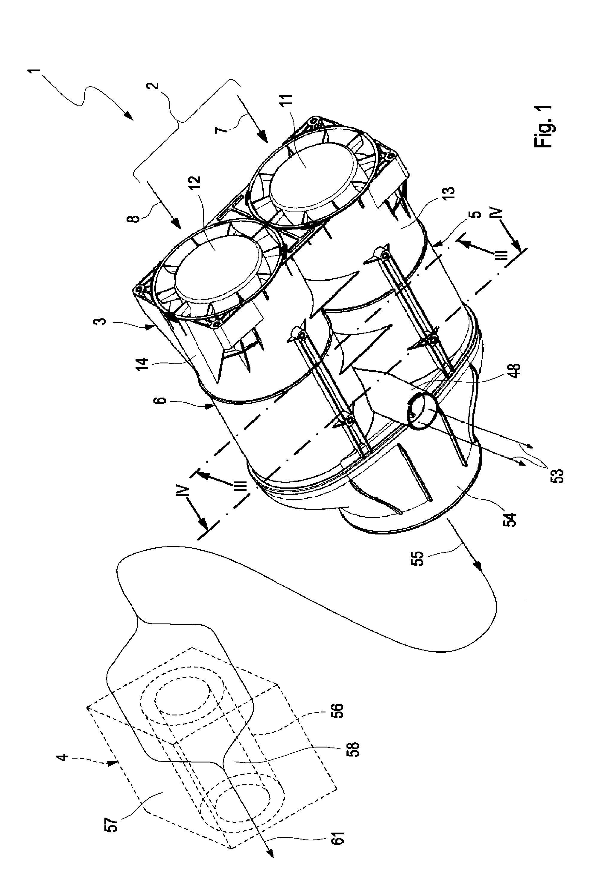
[0043]FIG. 1 shows in a perspective view an arrangement 1 for purifying an intake air 2 of an internal combustion engine, not illustrated.

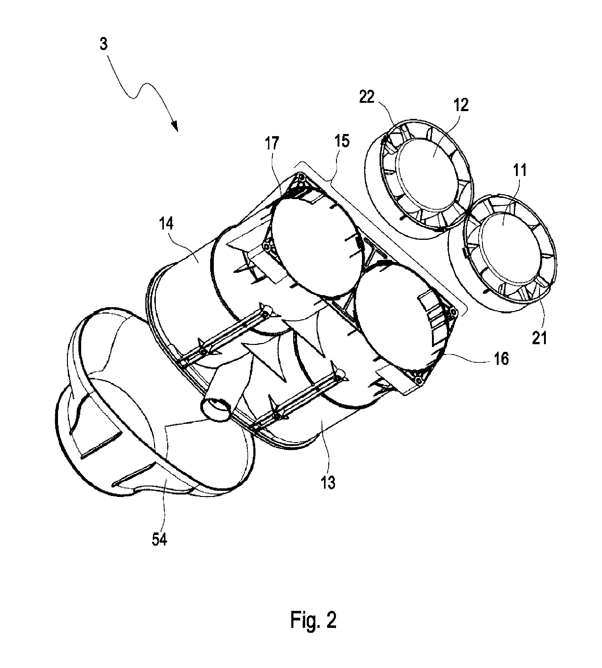
[0044]The arrangement 1 comprises a pre-separator in the form of a separating device 3 and a main filter 4. The separating device 3 will be further explained in more detail in the following with the aid of FIGS. 2-4, wherein FIG. 2 is an exploded view of the separating device 3 of FIG. 1, FIG. 3 is a section III-III of FIG. 1, and FIG. 4 a section IV-IV of FIG. 1.

[0045]The separating device 3 comprises two cyclone cells 5, 6. The intake air 2 comprises two raw air streams 7, 8 wherein the raw air stream 7 is supplied to the cyclone cell 5 and the raw air stream 8 to the cyclone cell 6. The cyclone cells 5, 6 are embodied in the embodiment in inline cyclone cell configuration. A respective cyclone cell 5, 6 comprises a guide apparatus 11, 12 and a main tube 13, 14.

[0046]The main tubes 13, 14 are connected to each other to a monolithic housing 15, a...


PUM


Abstract

A separating device (3) for separating particles from an intake air (2) of an internal combustion engine, comprising two cyclone cells (5, 6) which are designed to cause two raw air streams (7, 8) containing the intake air (2) to rotate oppositely and a discharge device (49) which is designed to guide an exhaust air stream (35, 36) containing the particles tangentially away from a respective cyclone cell (5, 6) and to combine the exhaust air streams (35, 36) to a common exhaust air stream (53).

Description

CROSS REFERENCE TO RELATED APPLICATIONS[0001]This application is a Non-Provisional of Provisional Application No. 61 / 701,065 filed Sep. 14, 2012, the entire disclosure of which is incorporated herein by reference.TECHNICAL FIELD[0002]The present invention concerns a separating device for separating particles from an intake air of an internal combustion engine. Moreover, the present invention concerns an arrangement for purifying an intake air of an internal combustion engine.BACKGROUND[0003]Cyclone cells, which are also referred to as cyclone, cyclone filter, cyclone separator or centrifugal separator, serve to separate solid or liquid particles contained in fluids. A fluid flowing into a cyclone cell is guided in such a way that centrifugal forces accelerate the particles that are to be separated from the fluid in outward direction and feed them to a discharge device. For generating the centrifugal forces, usually guide apparatus are used which comprise guide vanes that generate a ...

Claims


Application Information

Patent Timeline
IPC IPC(8): F02M35/04
CPCF02M35/044F02M35/024F02M35/0223F02M35/0215F02M35/0216B01D45/16B01D46/521B01D45/12B04C3/06B01D50/20
Inventor OELPKE, REINHARD
Owner MANN HUMMEL GMBH
Why Eureka
Try Eureka