Electronic torque wrench

Active Publication Date: 2014-06-19
KABO TOOL COMPANY
View PDF4 Cites 4 Cited by
  • Summary
  • Abstract
  • Description
  • Claims
  • Application Information

AI Technical Summary

Benefits of technology

[0008]It is therefore a primary object of the present invention to pr

Problems solved by technology

This leads to limitation of use of the wrench.
For example, it is impossible to use the wrench in a narrow space.
However, such des

Method used


Image

  • Electronic torque wrench
  • Electronic torque wrench
  • Electronic torque wrench

Examples


Embodiment Construction

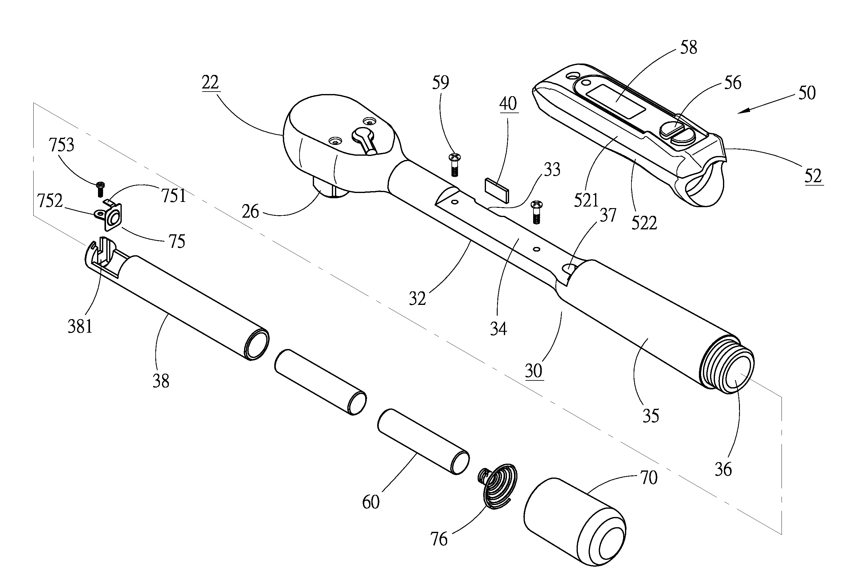
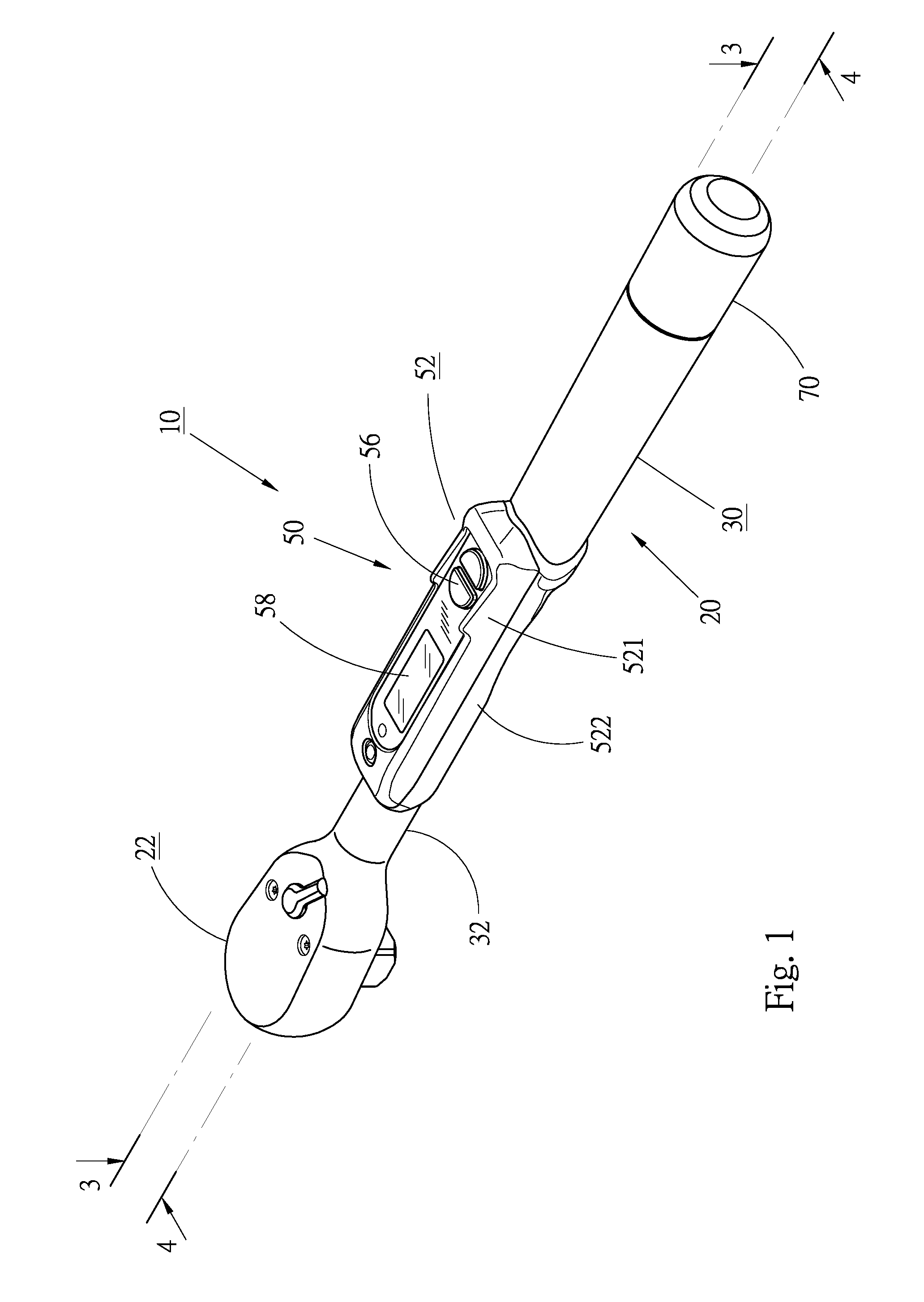
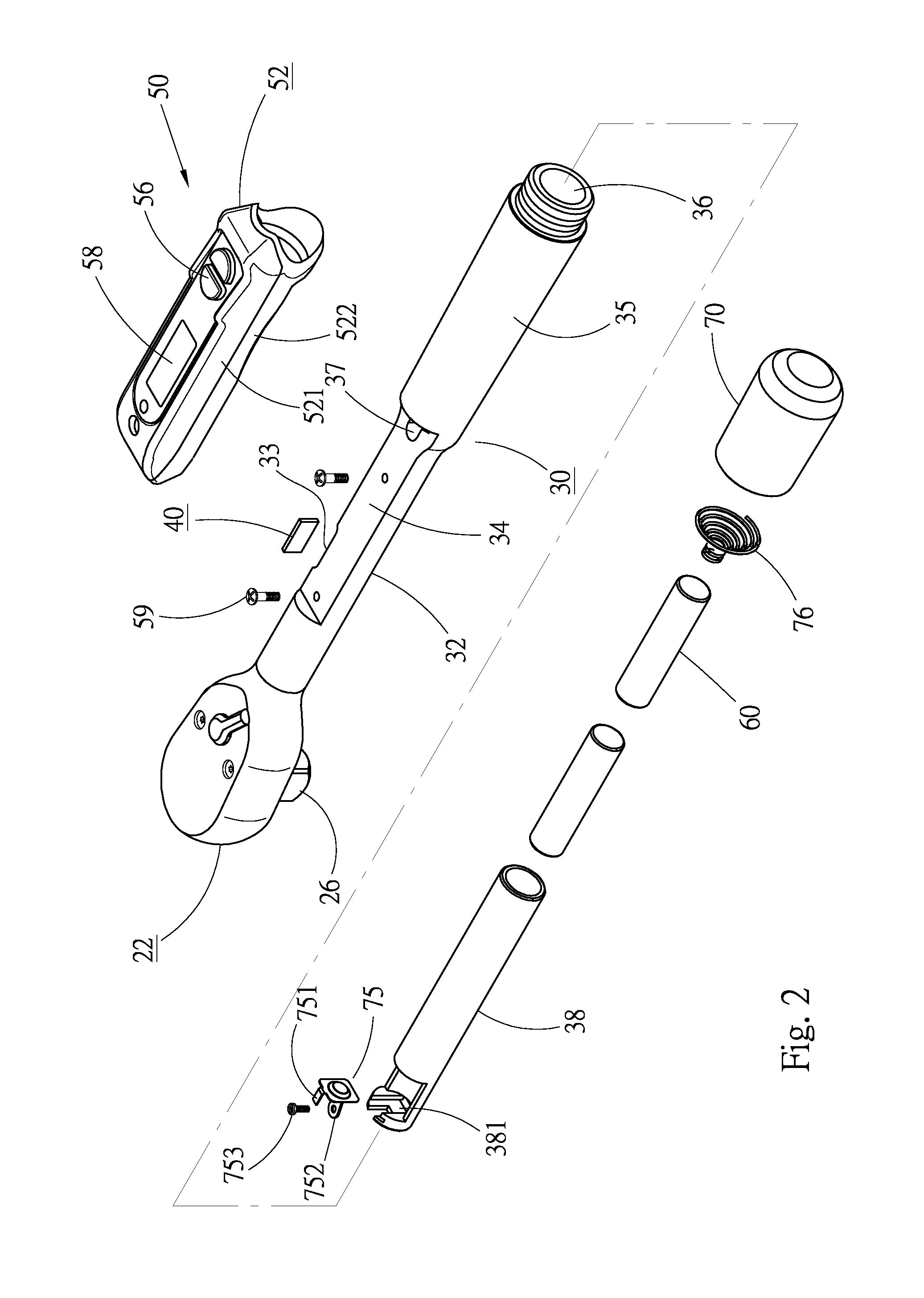
[0019]Please refer to FIGS. 1 and 2. The electronic torque wrench 10 of the present invention includes a wrench main body 20, a torque sensor 40 mounted on the main body 20, an electronic operation / control device 50 mounted on the main body 20 and one or more cells 60 mounted in the main body 20.

[0020]The wrench main body 20 is made of metal material, having a head section 22 and a shank body 30 connected with the head section 22. The head section 22 and the shank body 30 can be integrally formed or pivotally connected with each other. A drive assembly is disposed in the head section 22 for wrenching a threaded member such as a nut or a bolt. Please refer to FIG. 3. The drive assembly generally is, but not limited to, a ratchet assembly having a ratchet 24. The ratchet 24 has a polygonal hole for fitting on a threaded member. Alternatively, the ratchet 24 is provided with an insertion post 26 for connecting with a socket.

[0021]Please now refer to FIGS. 2 to 4. The shank body 30 has ...


PUM


Abstract

An electronic torque wrench includes: a wrench main body including ahead section and a shank body, at least one recess being formed on a wall face of one side of the shank body, a top face of the shank body being inward depressed to form a platform, a rear end of the shank body being inward recessed to form a cavity for placing cells therein, a through hole being formed on the shank body in communication with the platform and the cavity; at least one torque sensor disposed in the recess; and an electronic operation/control device disposed on the platform. The outward protruding volume of the operation/control device is reduced to minify the total volume of the wrench and the platform and the recess enhance the flexion of the shank body.

Description

BACKGROUND OF THE INVENTION[0001]1. Field of the Invention[0002]The present invention relates generally to an electronic torque tool, and more particularly to an electronic torque wrench.[0003]2. Description of the Related Art[0004]The conventional torque wrenches can be classified into mechanical torque wrenches and electronic torque wrenches. The electronic torque wrench is equipped with electronic components and a liquid crystal screen for showing the torque value and other data.[0005]Taiwan Patent No. 1341769 discloses a conventional electronic torque wrench having a shank body 30 and a housing 20 mounted on the outer circumference of the shank body 30. The electronic components are arranged in a front casing section 21 of the housing 20. One or two sensors 40 are disposed on the circumference of the shank body 30 to detect the flexion of the shank body 30 for a user to know the torque value of the wrench.[0006]In the above electronic torque wrench, the electronic components are...

Claims


Application Information

Patent Timeline
IPC IPC(8): B25B23/142
CPCB25B23/1425
Inventor HSIEH, CHIH-CHING
Owner KABO TOOL COMPANY
Why Eureka
Try Eureka