Eureka AIR delivers breakthrough ideas for toughest innovation challenges, trusted by R&D personnel around the world.

Electronic module

Active Publication Date: 2014-06-19
HTC CORP
View PDF1 Cites 10 Cited by
  • Summary
  • Abstract
  • Description
  • Claims
  • Application Information

AI Technical Summary

Benefits of technology

The patent text describes a way to make an electronic module with two conductive fences that are directly joined together. This allows for taller electronic components, which pushes the overall thickness of the module down. The technical effect is a flatter and more compact electronic module.

Problems solved by technology

However, due to the increasing demands for operational capabilities as well as other functions of the handheld electronic device, it is no longer sufficient to hold electronic components in the electronic device with an individual circuit board.
As a result, it is difficult for the electronic device having the electronic module 100 to satisfy the requirement for compactness and light weight.

Method used


Image

  • Electronic module
  • Electronic module
  • Electronic module

Examples


Embodiment Construction

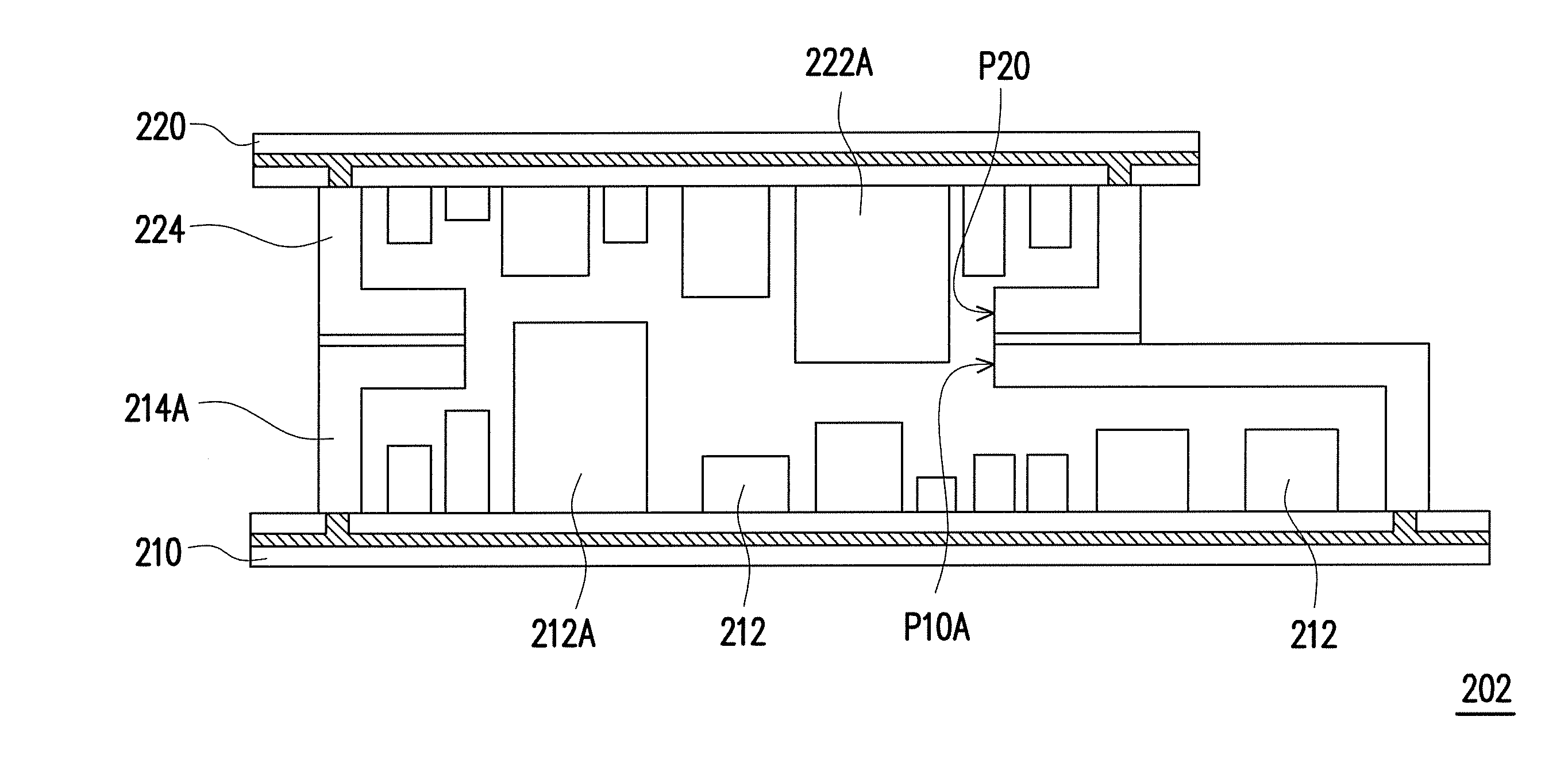
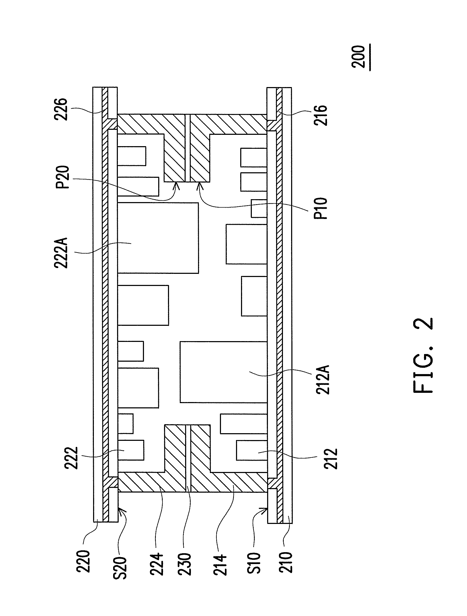
[0015]FIG. 2 is a schematic cross-sectional view illustrating an electronic module according to an embodiment of the invention. With reference to FIG. 2, the electronic module 200 described in the present embodiment includes a first circuit board 210, a plurality of first electronic components 212, a first conductive fence 214, a second circuit board 220, a plurality of second electronic components 222, and a second conductive fence 224. According to the present embodiment, the electronic module 200 is applicable to electronic devices complying with the requirement for compactness and light weight, such as mobile phones, tablet PCs, and so forth.

[0016]The first circuit board 210 has a first surface S10. The first electronic components 212 are located on the first surface S10 of the first circuit board 210. The first conductive fence 214 is located on the first surface S10 of the first circuit board 210 and encloses the first electronic components 212. Certainly, other electronic com...


PUM


Abstract

An electronic module includes a first circuit board having a first surface, a second circuit board having a second surface, first electronic components on the first surface, second electronic components on the second surface, a first conductive fence, and a second conductive fence. The first conductive fence encloses the first electronic components and has a first opening exposing the first electronic components. The second conductive fence encloses the second electronic components and has a second opening exposing the second electronic components. The first opening of the first conductive fence joints the second opening of the second conductive fence, such that the first electronic components and the second electronic components are surrounded by the first circuit board, the second circuit board, the first conductive fence, and the second conductive fence. At least one of the first electronic components is higher than the first conductive fence.

Description

BACKGROUND OF THE INVENTION[0001]1. Field of the Invention[0002]The application relates to an electronic module. More particularly, the invention relates to a stacked-type electronic module.[0003]2. Description of Related Art[0004]With the advancement of science and technology, human beings tend to rely on electronic devices to a greater extent. To meet the requirement for light weight, slimness, compactness, and great operational performance, various handheld electronic devices, such as ultra mobile personal computers (UMPCs), tablet PCs, pocket PCs, personal digital assistants (PDAs), cell phones, and notebook PCs, have been developed.[0005]However, due to the increasing demands for operational capabilities as well as other functions of the handheld electronic device, it is no longer sufficient to hold electronic components in the electronic device with an individual circuit board. Hence, a design of two stacked circuit boards has been applied to electronic modules in some electro...

Claims


Application Information

Patent Timeline
IPC IPC(8): H05K7/06
CPCH05K7/06G06F1/1658H04M1/0274H05K1/0218H05K1/144H05K2201/042H05K2201/0723H05K2201/1031H05K2201/10371H05K2201/2018Y02P70/50G06F1/16H04M1/00
Inventor CHUANG, I-CHENGCHEN, CHIEN-HUNGLI, CHIH-HUNGCHEN, CHENG-TE
Owner HTC CORP
Why Eureka
Eureka Blog
Learn More