Optical Lens

Inactive Publication Date: 2014-06-19
TPV DISPLAY TECH (XIAMEN) CO LTD
View PDF8 Cites 17 Cited by
  • Summary
  • Abstract
  • Description
  • Claims
  • Application Information

AI Technical Summary

Benefits of technology

[0028]The optical lens of the present invention includes the light diffusing structure disposed on the curved surface of the bottom surface, which makes the distribution of light projected on the light receiving surface more evenly and avoids the occurrence of the bright circle caused by the gap formed from assembly tolerance of the optical lens and the light source. Another optical lens of the invention includes the light di

Problems solved by technology

Which causes the intensity of light near the central axis is higher, such that the distribution of light is unevenly.
But the secondary lens of the patent requires very high level of machining accuracy

Method used


Image

  • Optical Lens
  • Optical Lens
  • Optical Lens

Examples


Example

The First Embodiment

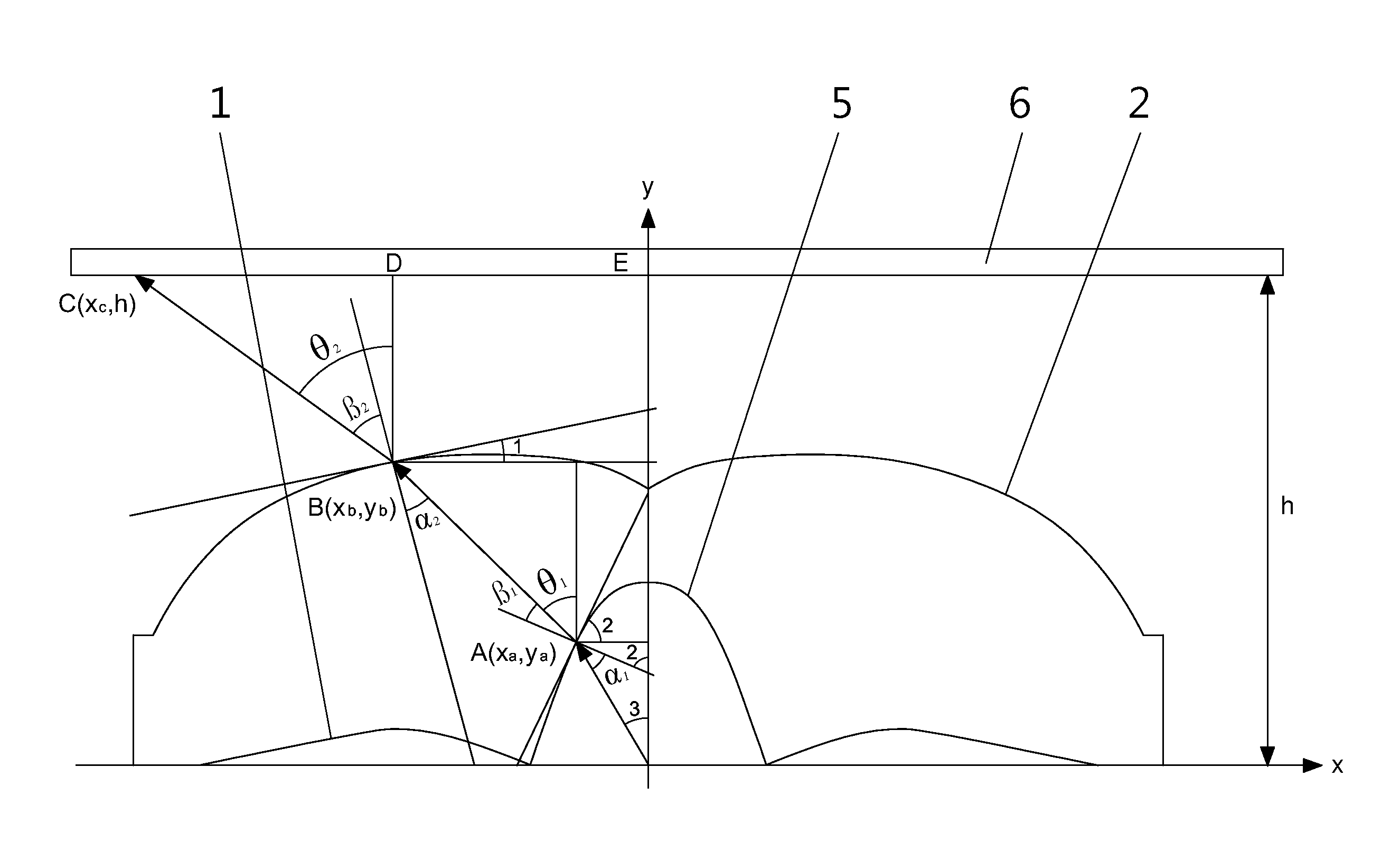
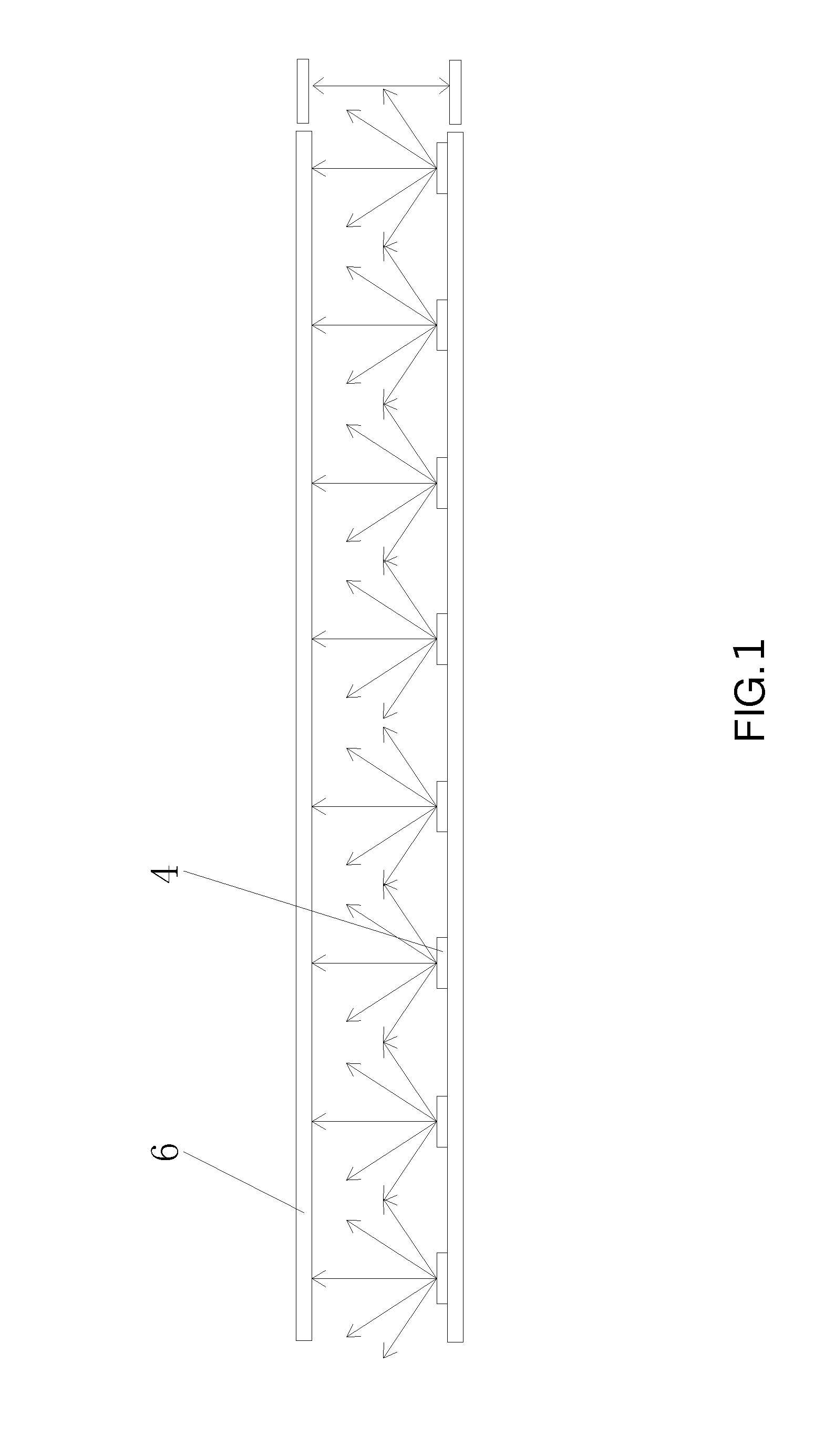
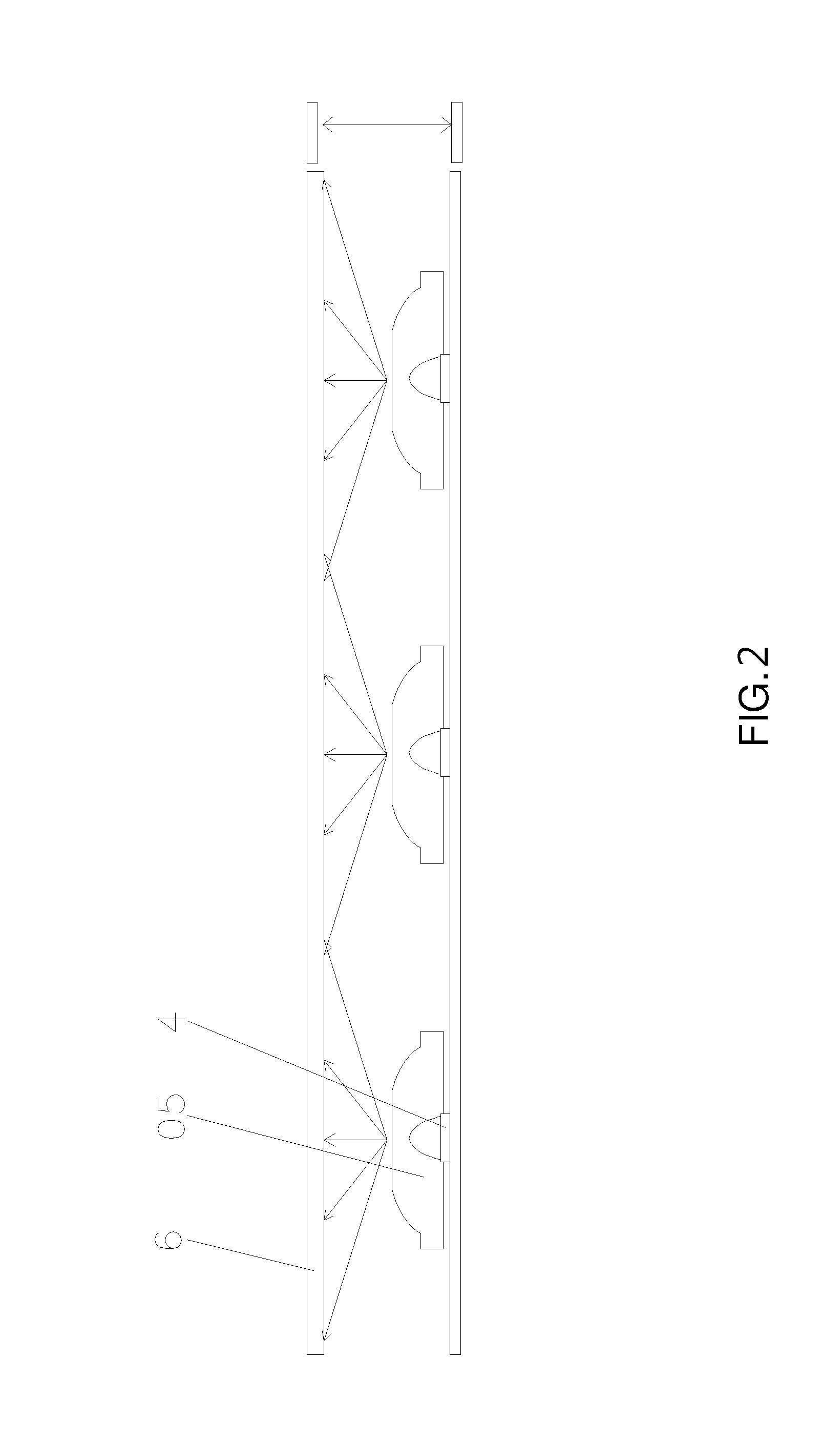
[0067]Please refer to FIG. 13. In the first embodiment, the light diffusing structure 5 is disposed on the curved surface of the bottom surface 1 of the optical lens. Part of light rays “a” refract outward when passing through the incidence surface 3 then refract outward again when passing through the emergence surface 2, so that light would be diffused. Part of light rays “b” reflect when reaching the emergence surface 2. When reaching the curved surface on the bottom surface 1, the reflected light rays “b” reflects again toward outsides and away from the center axis of the optical lens. As a result, the intensity of light near the central axis can be decreased and the distribution of light near the central axis projected on the optical film set 6 (the light receiving surface) is evenly

[0068]When a gap between an emitting surface of the light source 4 and the bottom surface 1 of the optical lens is greater than 0, Part of light rays “c” which pass through the ga...

Example

The Second Embodiment

[0070]Please refer to FIG. 15. The light diffusing structure 5 includes a plurality of concave points distributed continuously. When passing through the gap and the bottom surface 1, light rays can be diffused by the light diffusing structure 5 so that the bright circle caused by the gap can be avoided.

[0071]Please refer to FIG. 16. The distance of the gap between the light source 4 and the bottom surface 1 of the optical lens is 0.2 mm. The optical lens does not have any light diffusing structure (the same as the optical lens shown in FIG. 8). The bright circle is obvious in the brightness distribution.

[0072]Please refer to FIG. 17. The distance of the gap between the light source 4 and the bottom surface 1 of the optical lens is 0.2 mm. FIG. 17 is a diagram of brightness distribution of the optical lens which has light diffusing structure 5 disposed on the curved surface of the bottom surface 1 and including the plurality of concave points distributed continuo...

Example

The Third Embodiment

[0074]Please refer to FIG. 18. The light diffusing structure 5 includes a plurality of convex points distributed continuously. When passing through the gap and the bottom surface 1, light rays can be diffused by the light diffusing structure 5 so that the bright circle caused by the gap can be avoided.

[0075]Please refer to FIG. 19. The distance of the gap between the light source 4 and the bottom surface 1 of the optical lens is 0.2 mm. The optical lens does not have any light diffusing structure. As shown in FIG. 19, the bright circle on the optical film set 6 (the light receiving surface) is obvious.

[0076]Please refer to FIG. 20. The distance of the gap between the light source 4 and the bottom surface 1 of the optical lens is 0.2 mm. The optical lens has light diffusing structure 5 disposed on the curved surface of the bottom surface 1 and including the plurality of convex points. As shown in FIG. 20, the bright circle projected on the optical film set 6 (the ...


PUM


Abstract

The invention relates to an optical lens utilized for disposing above a light source. The optical lens has rotational symmetry relative to the central axis thereof. The central axis of the optical lens aligns with the center of the light source. The optical lens includes a bottom surface, an emergence surface with arc shape, an incidence surface with arc and concave shape, a curved surface with annular and concave shape and a light diffusing structure. The emergence surface connects a side of the bottom surface. The incidence surface connects another side of the bottom surface and lies in the middle of the bottom surface. The curved surface lies on the bottom surface and connects the incidence surface. The light diffusing structure is disposed on the curved surface. The invention improves the distribution of light projected on a light receiving surface and prevents a bright circle formed on the light receiving surface as a result of a gap that is formed by assembly tolerance of the optical lens and the light source.

Description

BACKGROUND OF THE INVENTION[0001]1. Field of the Invention[0002]The present invention relates to an optical lens, and more particularly, to an optical lens applied to a backlight module.[0003]2. Description of the Prior Art[0004]Generally, the liquid crystal module utilized in the flat display device adopts the technique of thin film transistor liquid crystal display (TFT-LCD). The lighting type of TFT-LCD is inactive. The brightness the TFT-LCD need is provided by a backlight module. Then a colorful image the TFT-LCD displayed is achieved by the filtration of a color filter which filters the light provided by the backlight module.[0005]Please refer to FIG. 1. A conventional direct type backlight module includes a light source 4 and a optical film set 6. The light source 4 adopts light emitting diode (LED). LED becomes one of the most popular light sources that utilizes in the backlight module of TFT-LCD because of smaller size and less energy consuming. Since the type of the light ...

Claims


Application Information

Patent Timeline
IPC IPC(8): F21V5/04
CPCF21V5/045G02B3/02G02B19/0019G02B19/0066H01L33/58
Inventor LI, LI MEIZHENG, JUNYILIN, PO-IEM
Owner TPV DISPLAY TECH (XIAMEN) CO LTD
Why Eureka
Try Eureka