Thermally Stabilised Resonant Electro-Optic Modulator and Use Thereof

a resonant electro-optic modulator and thermal stabilisation technology, which is applied in the direction of optics, optical light guides, instruments, etc., can solve the problems of increasing the proneness of malfunctions of thermal stabilisation resonant electro-optic modulators, increasing the complexity of electrical components, and increasing the cost of the devi

Active Publication Date: 2014-06-19
INTERUNIVERSITAIR MICRO ELECTRONICS CENT (IMEC VZW)
View PDF10 Cites 12 Cited by
  • Summary
  • Abstract
  • Description
  • Claims
  • Application Information

AI Technical Summary

Benefits of technology

[0007]In certain aspects, the disclosure provides a thermally stabilised resonant electro-optic modulator which allows controlling the thermal stabilisation unit based on the output and the original input of the modulator which is less complicated.

Problems solved by technology

This additional transformation requires additional electrical components which are often relatively complicated, require additional power and make the thermally stabilised resonant electro-optic modulator more prone to malfunctions.

Method used


Image

  • Thermally Stabilised Resonant Electro-Optic Modulator and Use Thereof
  • Thermally Stabilised Resonant Electro-Optic Modulator and Use Thereof

Examples


Embodiment Construction

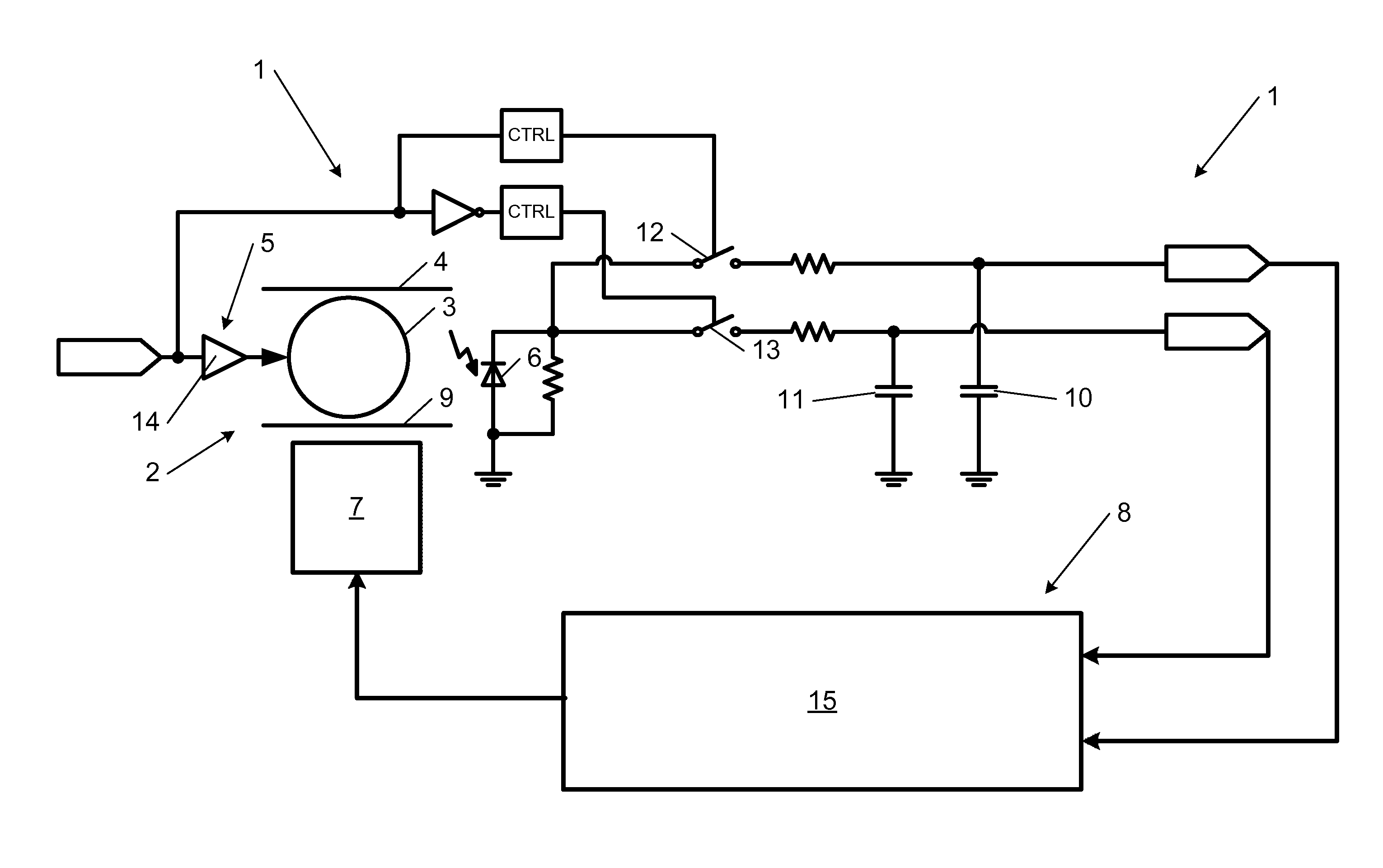
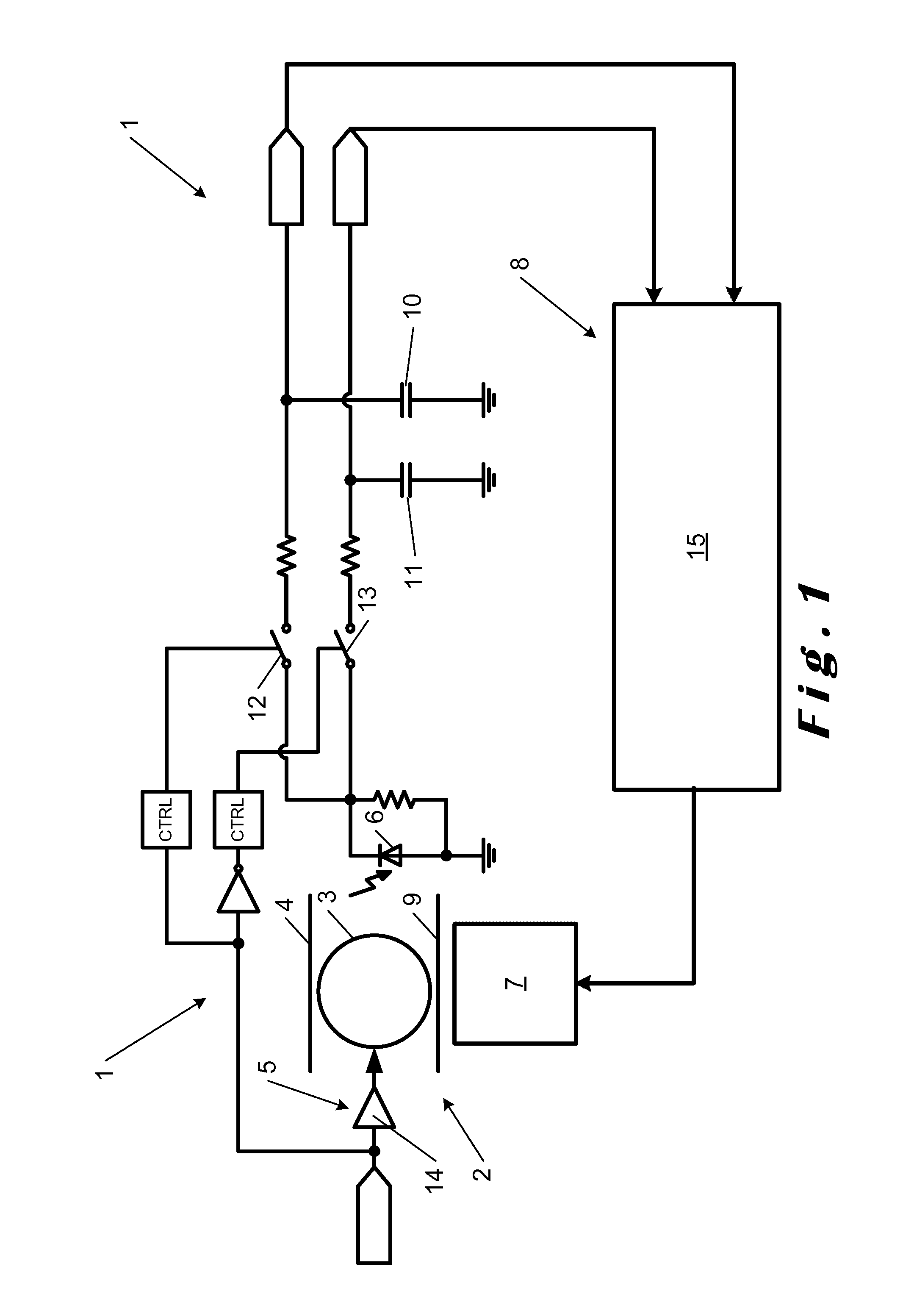
[0031]The present disclosure will be described with respect to particular embodiments and with reference to certain drawings but the disclosure is not limited thereto but only by the claims. The drawings described are only schematic and are non-limiting. In the drawings, the size of some of the elements may be exaggerated and not drawn on scale for illustrative purposes. The dimensions and the relative dimensions do not necessarily correspond to actual reductions to practice of the disclosure.

[0032]Furthermore, the terms first, second, third and the like in the description and in the claims, are used for distinguishing between similar elements and not necessarily for describing a sequential or chronological order. The terms are interchangeable under appropriate circumstances and the embodiments of the disclosure can operate in other sequences than described or illustrated herein.

[0033]Moreover, the terms top, bottom, over, under and the like in the description and the claims are use...


PUM

PropertyMeasurementUnit
wavelengthaaaaaaaaaa
temperatureaaaaaaaaaa
thresholdaaaaaaaaaa

Abstract

Thermally stabilised resonant electro-optic modulator (1), wherein the temperature control unit (8) is provided for separately determining the first and the second intensities measured by the light sensor (6) at the first voltages and the second voltages respectively in function of time.

Description

CROSS-REFERENCE TO RELATED APPLICATIONS[0001]This application claims the benefit of priority of European Patent Application no. 12197140.2, filed Dec. 14, 2012, which is hereby incorporated herein by reference in its entirety.TECHNICAL FIELD[0002]The present disclosure relates to a thermally stabilised resonant electro-optic modulator and the use thereof.BACKGROUND ART[0003]It is expected that optical communications will significantly gain in importance as they allow for further increasing the communication speed and bandwidth for microscopic applications, such as chips, and allow further reduction of the footprint of such applications. To transform an electric signal to an optical signal an optical modulator is used, for example a resonant electro-optic modulator as described in Low voltage, Low-Loss, Multi-Gb / s Silicon Micro-Ring Modulator based on a MOS Capacitor by Joris Van Campenhout, Marianne Pantouvaki, Peter Verheyen, Shankar Selvaraja, Guy Lepage, Hui Yu, Willie Lee, Johan...

Claims


Application Information

Patent Timeline
Patent Type & Authority Applications(United States)
IPC IPC(8): G02F1/29
CPCG02F1/29G02B6/29398G02F1/0327G02F1/3132G02B6/12007G02B6/29341G02F2203/15G02F2203/21G02B6/29338
Inventor INGELS, MARK MARIA ALBERT
Owner INTERUNIVERSITAIR MICRO ELECTRONICS CENT (IMEC VZW)
Why Eureka
Try Eureka