
Systems and methods for nerve imaging

Active Publication Date: 2014-06-19
GENERAL ELECTRIC CO
View PDF0 Cites 20 Cited by
  • Summary
  • Abstract
  • Description
  • Claims
  • Application Information

AI Technical Summary

Benefits of technology

The present patent describes an imaging system that can produce two fluorescence images at different wavelengths that are used to determine the difference between the fluorescence emissions of a target species and a background species in a subject. The system then generates an intermediate image by multiplying or dividing the first fluorescence image with the determined difference, and reconstructs a background-subtracted image by subtracting the intermediate image from the second fluorescence image. The technical effect of this system is that it allows for more accurate and reliable imaging of target species in a subject, even in the presence of background species.

Problems solved by technology

Surgical procedures, including laparoscopic studies and interventions, are prone to cause iatrogenic nerve damage, which in turn, may lead to loss of function, loss of sensation, muscle atrophy and / or chronic neuropathy in a patient.
Often, such damage is caused inadvertently during surgery due to poor visibility of a target species, for example nerves, in comparison to surrounding tissues.
Although the fluorophores are designed to label a particular species, for example nerves or tumor margins, nonspecific or competitive binding of the fluorophores may result in poor signal-to-background ratio (SBR) and / or limited dynamic range.
Accordingly, many bright fluorophores that specifically label biological targets and have favorable biological and chemical properties may be eliminated from the development pipeline due to inadequate SBR, thus resulting in a dearth of efficient fluorophores.
Although, such conventional approaches may allow generation of fluorescence images indicative of spatially varying absorption in the imaged tissue, such approaches still fail to provide significant improvement in suppressing unintentionally labeled background tissues, while allowing for reliable identification of target biological tissues during imaging.

Method used


Image

  • Systems and methods for nerve imaging
  • Systems and methods for nerve imaging
  • Systems and methods for nerve imaging

Examples


Embodiment Construction

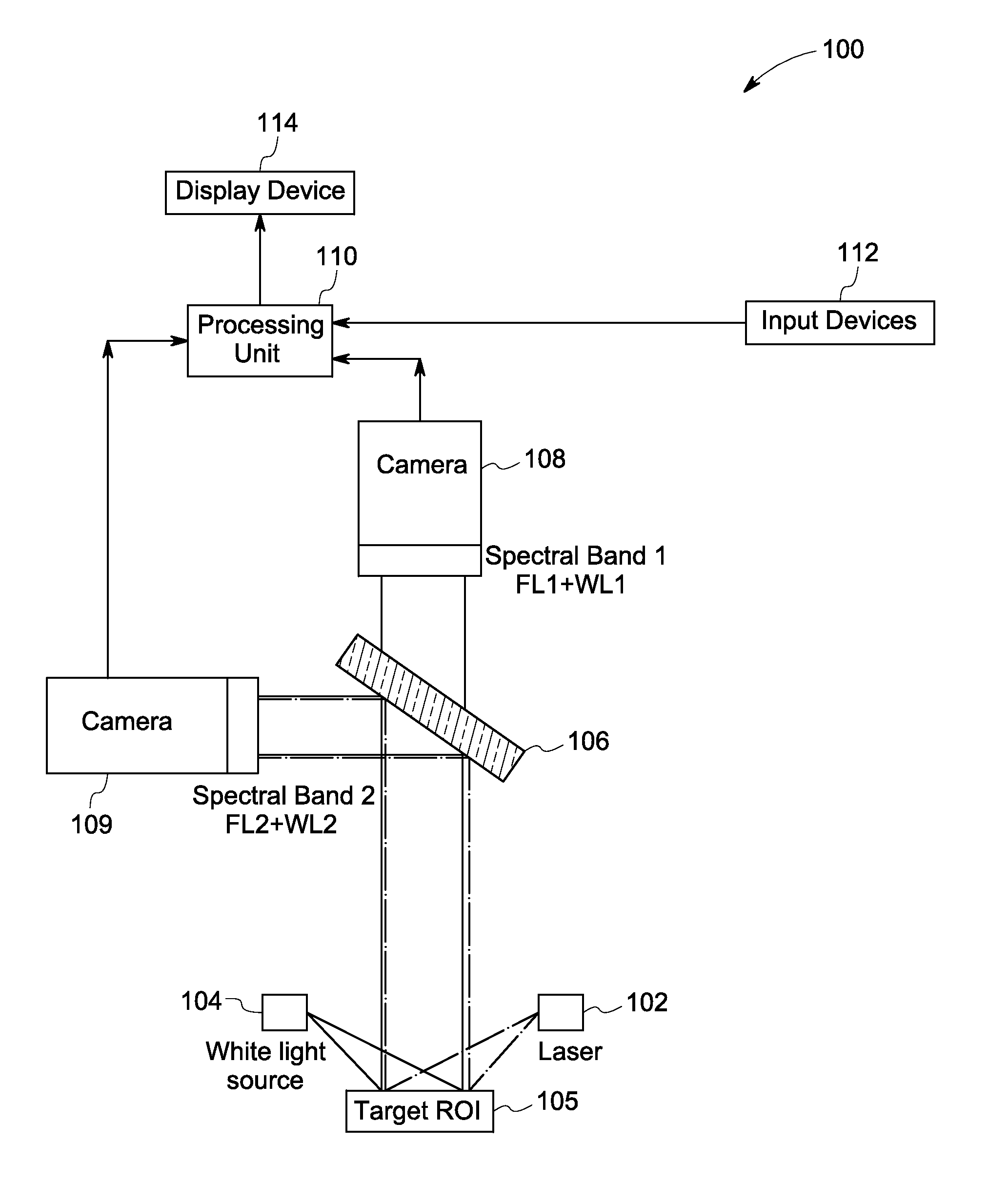
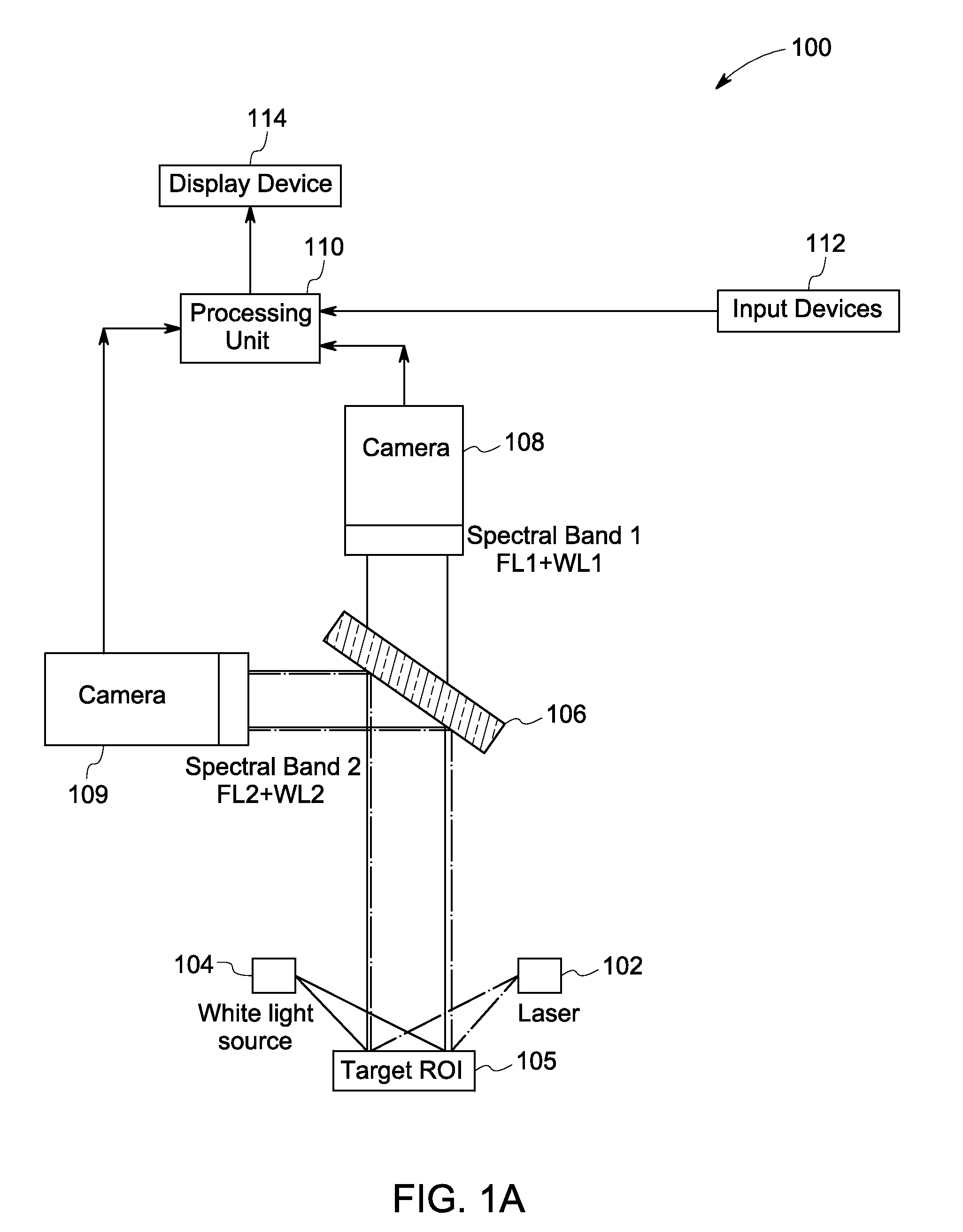
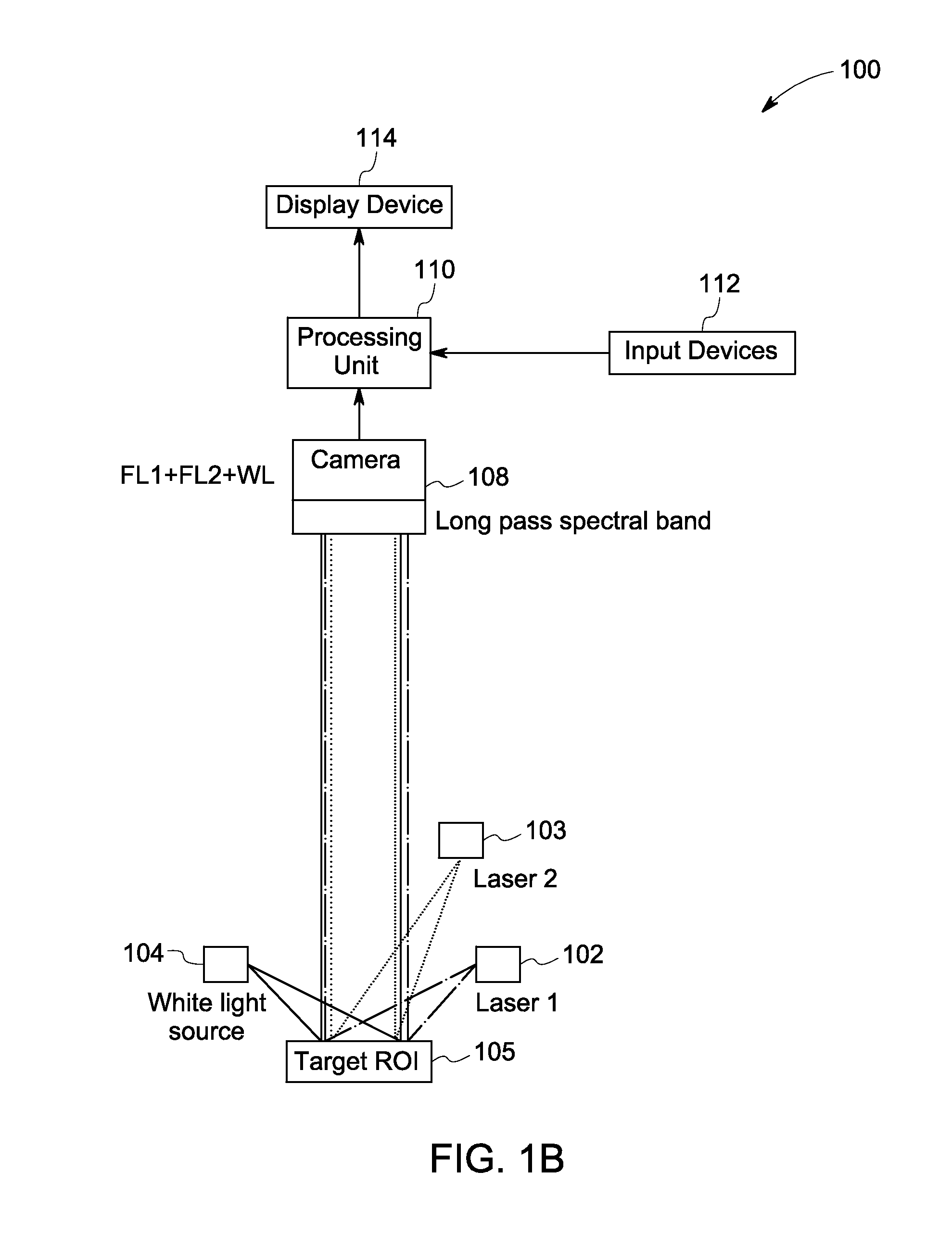
[0019]The following description presents system and methods for fluorescence imaging for use in open and / or minimally-invasive surgical (MIS) procedures. Particularly, certain embodiments illustrated herein describe efficient methods and systems that provide significant improvement in suppressing unintentionally labeled background tissues, while allowing for reliable identification of targeted biological tissues during fluorescence imaging.

[0020]For discussion purposes, embodiments of the present system are described with reference to an optical imaging system configured to generate high quality fluorescence images for visualizing a target species, for example, nerves. However, in certain other embodiments, the present system may include any other suitable imaging device such as a laparoscope or a hand-held device configured to image other targeted species such as tumor margins based on specific implementation requirements. An exemplary environment that is suitable for practicing va...


PUM


Abstract

Systems and methods for imaging are presented. The method includes producing excitation light configured to induce fluorescence in an imaging agent that selectively binds to a target species in a region of interest (ROI) of a subject that also includes a background species. A first and a second spectral region are selected such that a determined difference between fluorescence corresponding to the target and the background species in the first spectral region differs from a corresponding difference in the second spectral region. First and second fluorescence images are generated from the fluorescence corresponding to the first and second spectral regions. Additionally, a fluorescence ratio for the background species in the first and second fluorescence image is determined. The first fluorescence image is then multiplied or divided with the determined ratio to generate an intermediate image that is subtracted from the second fluorescent image to reconstruct a background-subtracted image.

Description

STATEMENT OF GOVERNMENT INTEREST[0001]This invention was made with government support under R01 EB011872 awarded by National Institutes of Health through the National Institute of Biomedical Imaging and Bioengineering. The government has certain rights in the invention.BACKGROUND[0002]Embodiments of the present disclosure relate generally to fluorescence imaging, and more particularly to systems and methods for suppression of background species during nerve imaging.[0003]Surgical procedures, including laparoscopic studies and interventions, are prone to cause iatrogenic nerve damage, which in turn, may lead to loss of function, loss of sensation, muscle atrophy and / or chronic neuropathy in a patient. Often, such damage is caused inadvertently during surgery due to poor visibility of a target species, for example nerves, in comparison to surrounding tissues. Accordingly, certain imaging systems employ anatomical landmark identification for imaging the target species. Certain other sy...

Claims


Application Information

Patent Timeline
IPC IPC(8): A61B5/00
CPCA61B5/0071A61B5/6847A61B5/4893A61B2505/05A61B2576/02A61B1/043A61B1/0638A61B2090/373A61B90/361A61B90/37G16H30/40A61B1/000094A61B17/00
Inventor KIM, EVGENIA MIKHAILOVNAYAZDANFAR, SIAVASHTAN HEHIR, CRISTINA ABUCAY
Owner GENERAL ELECTRIC CO
Learn More