

Imaging Device and Electronic Device
a technology of electronic devices and imaging devices, applied in the field of imaging devices, can solve the problems of large amount of power required for digital image processing for data compression, and achieve the effect of reducing the amount of transmission data
- Summary
- Abstract
- Description
- Claims
- Application Information
AI Technical Summary
Benefits of technology
Problems solved by technology
Method used
Image


Examples
embodiment 1
[0084]In this embodiment, an imaging device that is one embodiment of the present invention will be described with reference to drawings.
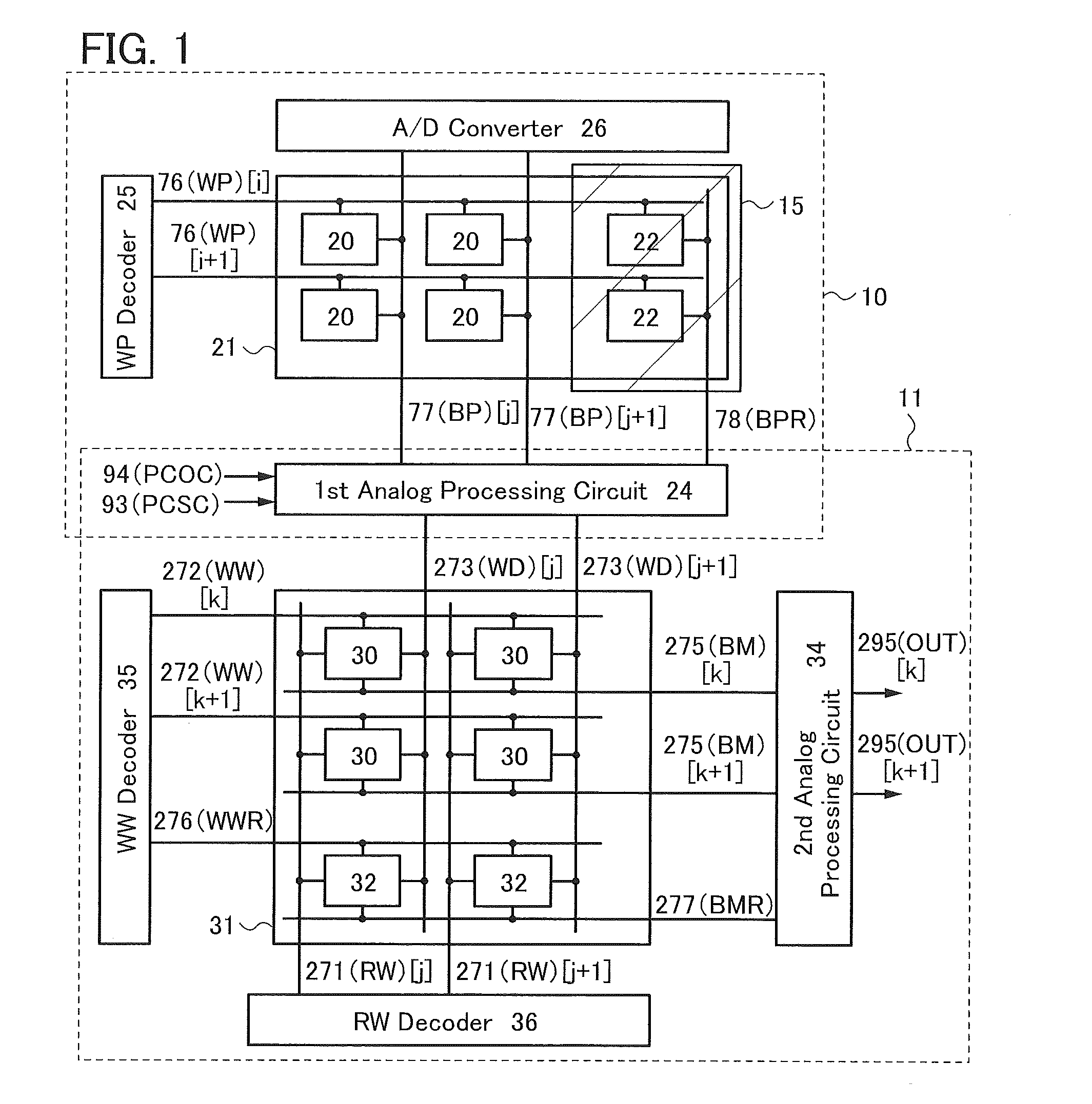
[0085]FIG. 1 is a block diagram illustrating an imaging device of one embodiment of the present invention. The imaging device includes an imaging portion 10 that mainly performs an imaging operation and an arithmetic portion 11 that mainly performs a data conversion operation.
[0086]The imaging portion 10 includes a pixel array 21 in which pixels 20 used for imaging and reference pixels 22 used for image processing are arranged in a matrix, a row decoder 25, and an AID converter 26. The arithmetic portion 11 includes a memory element array 31 in which memory elements 30 and reference memory elements 32 are arranged in a matrix, an analog processing circuit 34, a row decoder 35, and a column decoder 36. Note that the imaging portion 10 and the arithmetic portion 11 are electrically connected to each other through an analog processing circuit 24. In o...
embodiment 2
[0284]In this embodiment, a transistor containing an oxide semiconductor that can be used in one embodiment of the present invention will be described with reference to drawings. In the drawings in this embodiment, some components are enlarged, reduced in size, or omitted for easy understanding.
[0285]FIGS. 33A and 33B are a top view and a cross-sectional view illustrating a transistor 101 of one embodiment of the present invention. FIG. 33A is the top view, and FIG. 33B illustrates a cross section taken along dashed-dotted line B1-B2 in FIG. 33A. A cross section in the direction of dashed-dotted line B3-B4 in FIG. 33A is illustrated in FIG. 35A. The direction of dashed-dotted line B1-B2 is referred to as a channel length direction, and the direction of dashed-dotted line B3-B4 is referred to as a channel width direction.
[0286]The transistor 101 includes an insulating layer 120 in contact with a substrate 115; an oxide semiconductor layer 130 in contact with the insulating layer 120;...
embodiment 3
[0349]In this embodiment, components of the transistors described in Embodiment 2 will be described in detail.
[0350]As the substrate 115, a glass substrate, a quartz substrate, a semiconductor substrate, a ceramic substrate, a metal substrate with an insulated surface, or the like can be used. Alternatively, a silicon substrate provided with a transistor, a photodiode, or the like can be used, and an insulating layer, a wiring, a conductor functioning as a contact plug, and the like may be provided over the silicon substrate. Note that when p-channel transistors are formed using the silicon substrate, a silicon substrate with n−-type conductivity is preferably used. Alternatively, an SOT substrate including an n−-type or i-type silicon layer may be used. In the case where a p-channel transistor is formed in the silicon substrate, it is preferable to use a silicon substrate in which a plane where the transistor is formed is a (110) plane orientation. Forming a p-channel transistor wi...
PUM
 Abstract
Description
Claims
Application Information