
Mass distribution measurement method and mass distribution measurement apparatus

Inactive Publication Date: 2015-04-30
CANON KK
View PDF1 Cites 8 Cited by
  • Summary
  • Abstract
  • Description
  • Claims
  • Application Information

AI Technical Summary

Benefits of technology

The present invention provides a method and apparatus for acquiring mass spectrum distribution information. This method corrects the fall of mass resolution due to inconsistency of data on secondary ion generation times, resulting in highly reliable images by mass spectrometry imaging.

Problems solved by technology

However, with the MALDI technique, the spatial resolution is limited to about tens of several micrometers because of the principle of utilization of matrix crystal on which it is based.
However, scanning type TOF-SIMS as described above is accompanied by a problem that a long period of time has to be spent to acquire a mass image over a broad area.
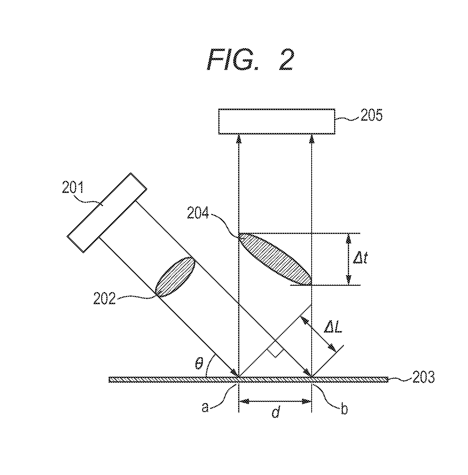
Then, as a result, there also arise in-surface variations of time of secondary ion generation from the specimen to give rise to a problem of a fall of mass resolution.
As such variations take place, there also arise (in-surface) variations of time of secondary ion detection to consequently lower the mass resolution to give rise to a problem that the two-dimensional mass distribution information in the area of measurement cannot be correctly observed.
Additionally, the signal intensities of the plurality of peaks for which m / z is known are not equal and hence a plurality of peaks with known m / z can hardly be detected by automatic detection.
In other words, this method does not assume the existence of variations of secondary ion generation time due to oblique incidence of primary ions in a two-dimensional collective mass spectrometry type mass spectrometry apparatus and hence the method of Japanese Patent Application Laid-Open No. 2011-149755 can hardly be applied to correction of such variance.

Method used


Image

  • Mass distribution measurement method and mass distribution measurement apparatus
  • Mass distribution measurement method and mass distribution measurement apparatus
  • Mass distribution measurement method and mass distribution measurement apparatus

Examples


example

[0057]Now, the present invention will be described further by way of a specific example. However, the present invention is by no means limited to the example.

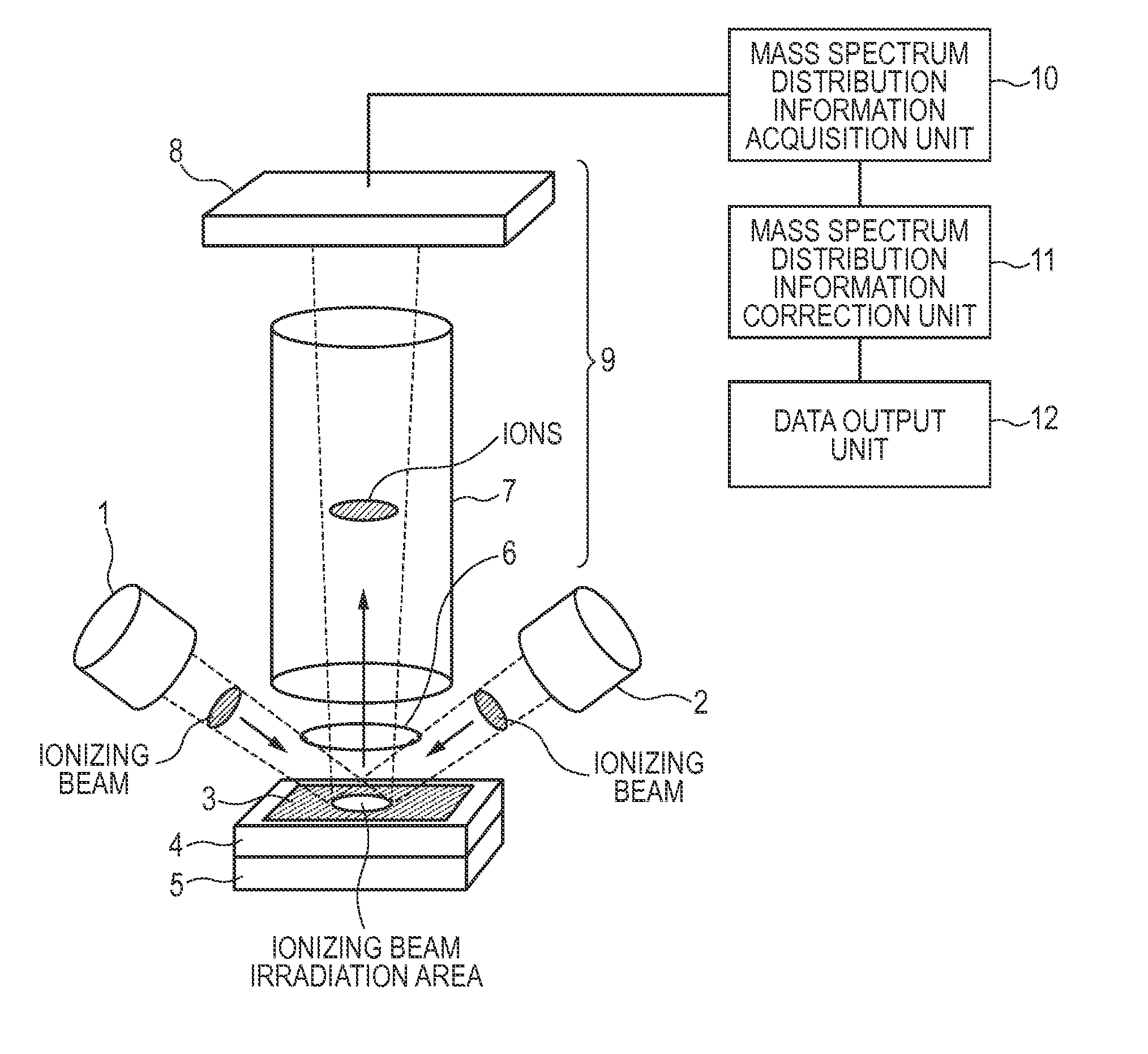
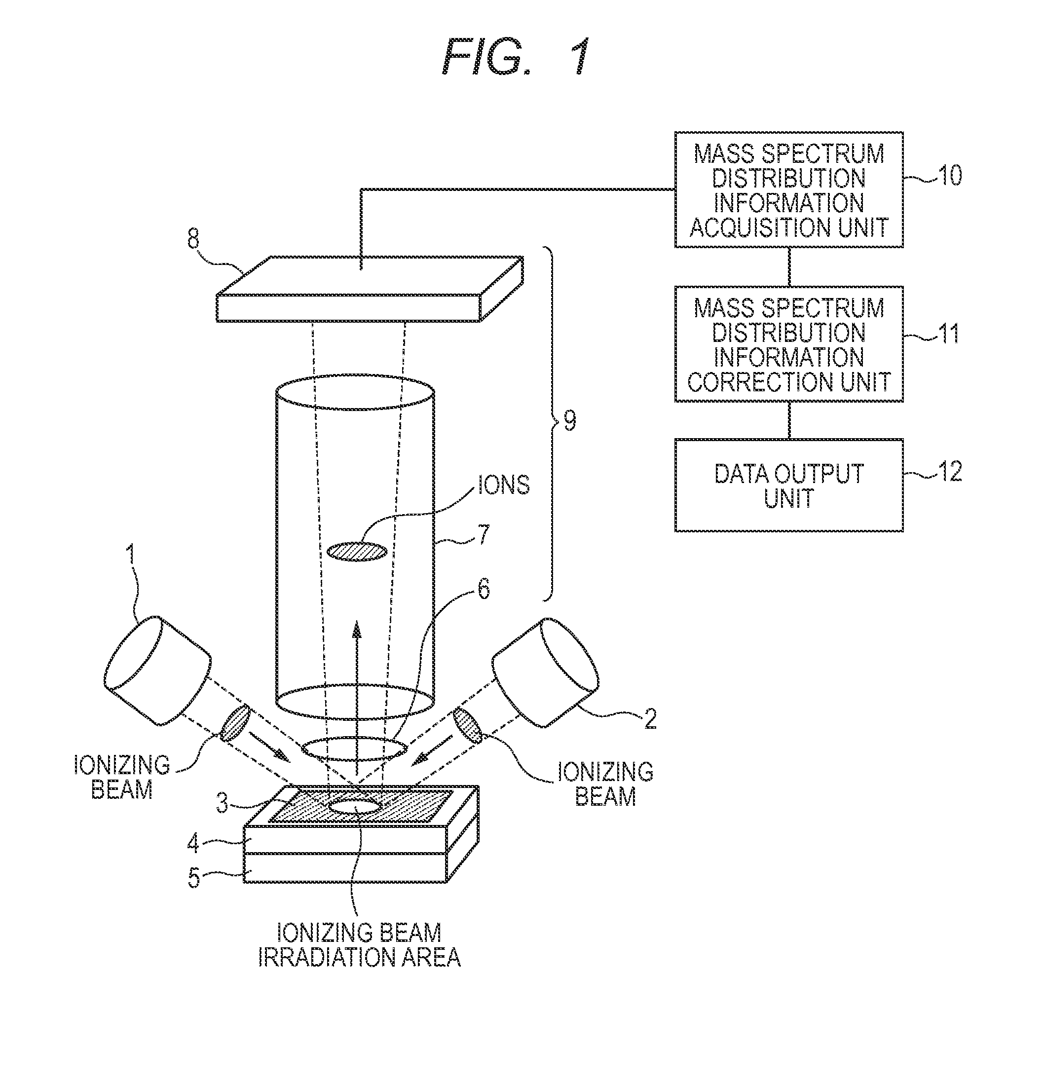
[0058]Now, the example of the present invention will be described below by referring to FIG. 1 and FIGS. 4A through 4C.

[0059]A glass substrate having an ITO evaporation layer (available from Sigma-Aldrich) is employed as substrate 4. A frozen cut piece of mouse liver (thickness: 5 microns) is placed on the substrate and made to adhere to the substrate as it becomes molten.

[0060]A laser is employed for the first ionizing beam irradiation unit 1 to output a first ionizing beam. The laser may be a YAG laser or the like. The unit 1 outputs a laser beam defocused to represent a beam diameter of about 1 mmφ. The unit 1 outputs a pulsed laser beam with a pulse period not greater than several ns. The unit 1 is made to emit a laser beam so as to strike the surface of the substrate 4 at an angle of 45°.

[0061]The second ionizing beam irra...


PUM


Abstract

Projection TOF mass spectrum distribution information is acquired by irradiating a first ionizing beam onto a surface of a specimen to acquire first mass spectrum distribution information on secondary ions generated from the specimen, irradiating a second ionizing beam onto the same surface to acquire second mass spectrum distribution information on secondary ions generated from the specimen, and correcting the second mass spectrum distribution information on the basis of the first mass spectrum distribution information.

Description

BACKGROUND OF THE INVENTION[0001]1. Field of the Invention[0002]The present invention relates to a method of acquiring mass distribution information on a specimen. The present invention also relates to an apparatus capable of displaying the acquired mass distribution information as a mass distribution image.[0003]2. Description of the Related Art[0004]Imaging mass spectrometry is realized by applying mass spectrometry and the development of imaging mass spectrometry is under way as analysis method of comprehensively visualizing two-dimensional distribution information on a large number of substances that constitute an analysis specimen, which may typically be a piece of biological tissue. Mass spectrometry is a technique of ionizing a specimen by irradiating the specimen with a laser beam or primary ions, isolating the ionized specimen (secondary ions) by utilizing the mass-to-charge ratio m / z (m: mass of secondary ion, z: valence of secondary ion) and obtaining a spectrum of second...

Claims


Application Information

Patent Timeline
IPC IPC(8): H01J49/00H01J49/40
CPCH01J49/0004H01J49/40H01J49/0031G01N23/2258
Inventor AOKI, NAOFUMIKYOGAKU, MASAFUMIIWASAKI, KOTA
Owner CANON KK
Learn More