System, method, and apparatus for powering, controlling, and communicating with LED lights using modified power-over-ethernet

a technology of power-over-ethernet and led lights, applied in the field of local smart grid systems, methods and apparatuses for powering, controlling, and communicating with light-emitting diodes (led) lights, can solve the problems of consuming energy, inconvenient supply of ac power, and devices that require more power

Inactive Publication Date: 2014-06-19
IDS IP HLDG
View PDF7 Cites 33 Cited by
  • Summary
  • Abstract
  • Description
  • Claims
  • Application Information

AI Technical Summary

Problems solved by technology

All of these devices require more power than USB offers and very often must be powered over longer runs of cable than USB permits.
PoE is presently deployed in applications where USB is unsuitable and where AC power would be inconvenient, expensive or infeasible to supply.
1) Cheaper cabling—even high quality outdoor category 5 cable is much cheaper than USB repeaters or AC wire. The task of meeting building code requirements to run AC power cable safely is eliminated.
2) A true gigabit connection to every device is possible, which exceeds USB 2.0 (400 Mbps) and current (as of 2011, 450 Mbps) AC powerline networking capabilities, and can be teamed for 2-gigabit or 4-gigabit speeds comparable to USB 3.0 throughput. A 10 Gigabit Power over Ethernet standard is also being created.
3) Global organizations can deploy PoE everywhere without concern for any local variance in AC power standards, outlets, plugs, or reliability. This makes a single standard office configuration much easier to maintain, monitor and update based on one standard plan.
4) Direct inje...

Method used


Image

  • System, method, and apparatus for powering, controlling, and communicating with LED lights using modified power-over-ethernet
  • System, method, and apparatus for powering, controlling, and communicating with LED lights using modified power-over-ethernet
  • System, method, and apparatus for powering, controlling, and communicating with LED lights using modified power-over-ethernet

Examples


Embodiment Construction

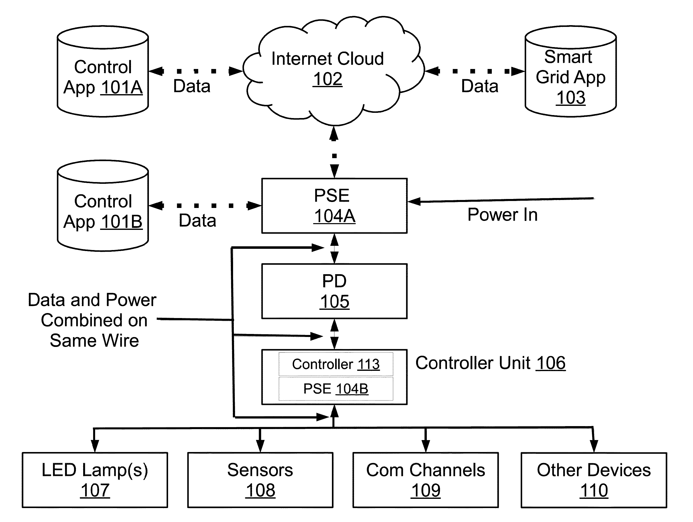
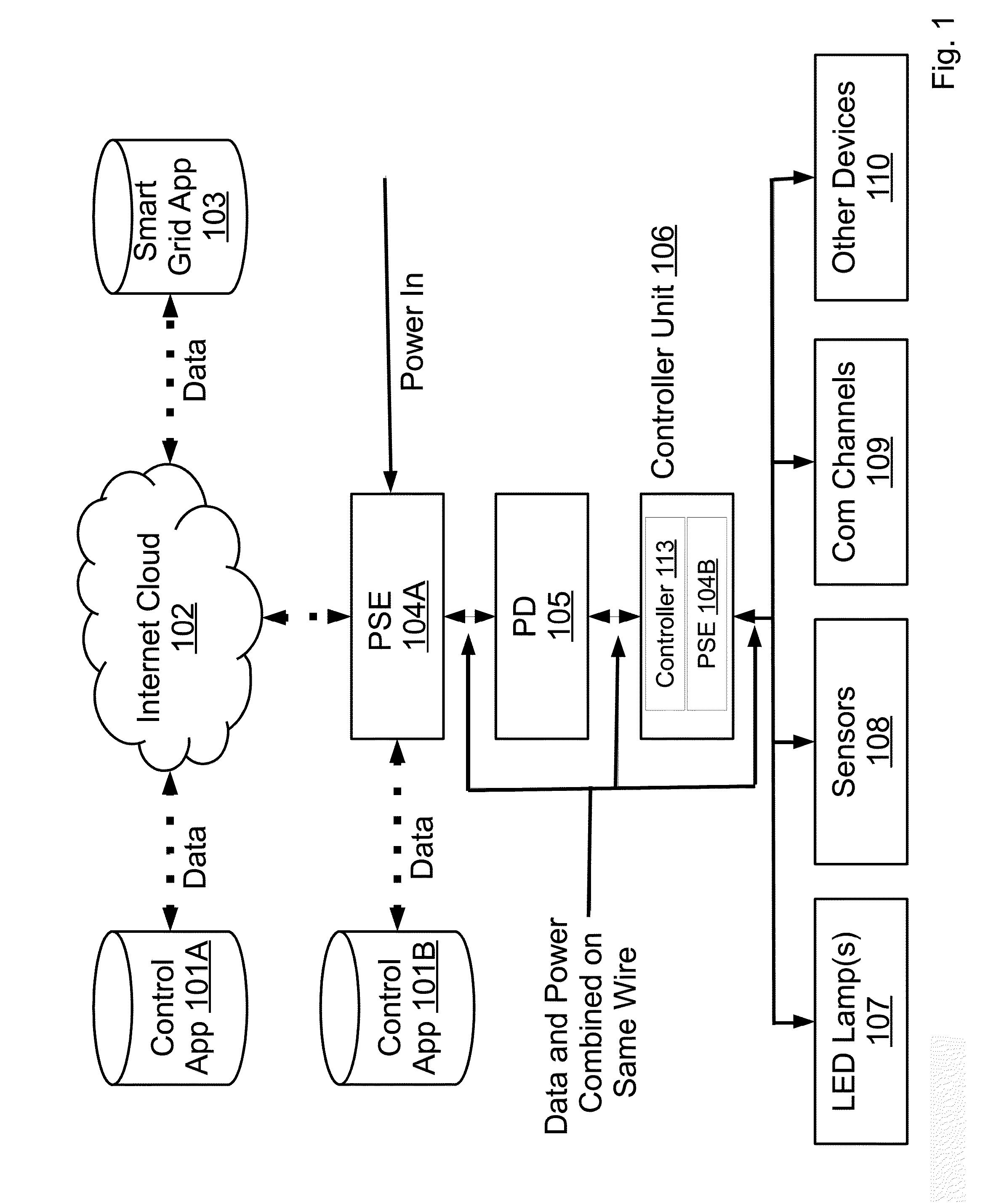
[0051]FIG. 1 is an illustration of the present invention.

[0052]Control App 101A is a program that resides on at least one computer, and is shown as accessible via a network, such as, but not limited to Internet Cloud 102. Control App 101A operates on a programmable machine designed to sequentially and automatically carry out a sequence of arithmetic or logical operations. Said programmable machine consists of some form of memory for data storage, at least one element that carries out arithmetic and logic operations, and a sequencing and control element that can change the order of operations based on the information that is stored. Control App 101A can send instructions to Controller Unit 106 to operate at least one LED Lamp 107; optionally, at least one Sensor 108; optionally at least one Communication Channel 109; and optionally Other Devices 110.

[0053]Control App 101B is a program that resides on at least one computer, and is shown as accessible via the same local network PSE 104...


PUM


Abstract

A smart grid system, method, and apparatus for powering, controlling, and communicating with light emitting diode (LED) lights using Modified Power over Ethernet (M-PoE), which includes capabilities such as the added capability for PoE ports to be turned on-off in response to a signal, and to be have a PoE port's output voltage regulated in response to a signal. M-PoE equipment includes PSE and PD equipment configured such as, but not limited to, midspans, end-spans, etc. The smart grid is a digitally enabled local electrical power distribution grid that is enabled to gather, distribute, and act on information about the behavior of all attached devices, including schedules, time of day, season, occupancy, etc., in order to improve the efficiency, reliability, and economics of electricity services. In addition, the smart grid may also communicate with the larger smart grid, and also may be controlled by the larger smart grid.

Description

CROSS-REFERENCE TO RELATED APPLICATIONS[0001]This application claims priority to U.S. Provisional Application, Ser. No. 61 / 797,877 filed Dec. 17, 2012 which is entitled System, Method, And Apparatus No. 1 For Powering, Controlling, And Communicating With LED Lights Using Combined Low Voltage Power / Data Cabling Excluding Ethernet Wiring.[0002]This application claims priority to U.S. Provisional Application, Ser. No. 61 / 797,873 filed Dec. 17, 2012 which is entitled System, Method, And Apparatus No. 7 For Powering, Controlling, And Communicating With LED Lights Using Combined Low Voltage Power / Data Cabling Excluding Ethernet Wiring.[0003]This application claims priority to U.S. Provisional Application, Ser. No. 61 / 797,872 filed Dec. 17, 2012 which is entitled System, Method, And Apparatus No. 8 For Powering, Controlling, And Communicating With LED Lights Using Combined Low Voltage Power / Data Cabling Excluding Ethernet Wiring.[0004]This application claims priority to U.S. Provisional Ap...

Claims


Application Information

Patent Timeline
IPC IPC(8): G05B15/02
CPCH04L12/10H04L12/12H04L12/40039H04L12/2818H04L12/2825H05B47/185H05B47/18H05B47/11H05B47/16H05B47/105Y02B20/40H05B45/30Y02B70/30Y04S20/20
Inventor SNYDER, DAVID M.
Owner IDS IP HLDG
Why Eureka
Try Eureka