
Apparatus for driving a scara robot and driving method thereof

a robot and scara technology, applied in the direction of dynamo-electric machines, dynamo-electric components, program-controlled manipulators, etc., can solve the problems of high cost, complicated linear structure of two motors, and complicated design and structure of the working axis

Active Publication Date: 2014-06-26
DELTA ELECTRONICS INC
View PDF25 Cites 30 Cited by
  • Summary
  • Abstract
  • Description
  • Claims
  • Application Information

AI Technical Summary

Benefits of technology

This patent describes an apparatus and method for driving a robot that can move in different directions. The apparatus includes a base, an articulated rotating arm, a horizontal rotating arm, a linear motor coil, and a vertical magnetic axis. The articulated rotating arm is connected to the base and can pivot. The horizontal rotating arm is connected to the articulated rotating arm and can pivot. The linear motor coil is connected to the horizontal rotating arm and can produce a magnetic force to move the vertical magnetic axis. The vertical magnetic axis passes through the linear motor coil and is moved back and forth on the horizontal rotating arm. The method involves applying electric power to the linear motor coil to produce the magnetic force and driving the vertical magnetic axis to achieve precise movements. The technical effects of this patent include improved precision and accuracy in the movement of the robot and reduced risk of falling.

Problems solved by technology

The working axis is complicated in design and structure.
a. High cost results from the complicated structures of the two motors and the linear way.
b. The heavy weight of the two motors and the linear way cause a larger loading of the horizontal rotating arm of the SCARA robot, and therefore the increased inertia reduces the stability of the horizontal rotating arm.
c. Conventionally one of the motors is used for driving the ball screw for the raising / lowering action, and the other motor is used for rotating the ball spline; the controllability of the hardware of the two motors cooperated with other equipment and the software used for driving the motors are very complicated, which lead to a high cost on the maintenance and repairing of the machine.
a. It is complicated and difficult to form the ball screw groove and the ball spline groove on the working axis, such that the complicated manufacturing process increases the cost.
b. The heavy weight of the two motors still makes a large burden on the horizontal rotating arm of the SCARA robot, and thus the increased inertia reduces the stability of the horizontal rotating arm.
c. It is complicated for the assembly of the ball screw groove and the ball spline groove on the working axis cooperated with the motor-driven ball screw nut and the ball spline nut, so are the controllability of the hardware of the two motors cooperated with other equipment and the software used for driving the motors. Therefore, it is difficult to reduce the cost of the assembling, maintenance and repairing of the machine.
Nowadays, the SCARA robot is to increasingly important on an automated factory, so that a high cost and complicated SCARA robot but with low stability is no longer meeting demands of the industry.

Method used


Image

  • Apparatus for driving a scara robot and driving method thereof
  • Apparatus for driving a scara robot and driving method thereof
  • Apparatus for driving a scara robot and driving method thereof

Examples


Embodiment Construction

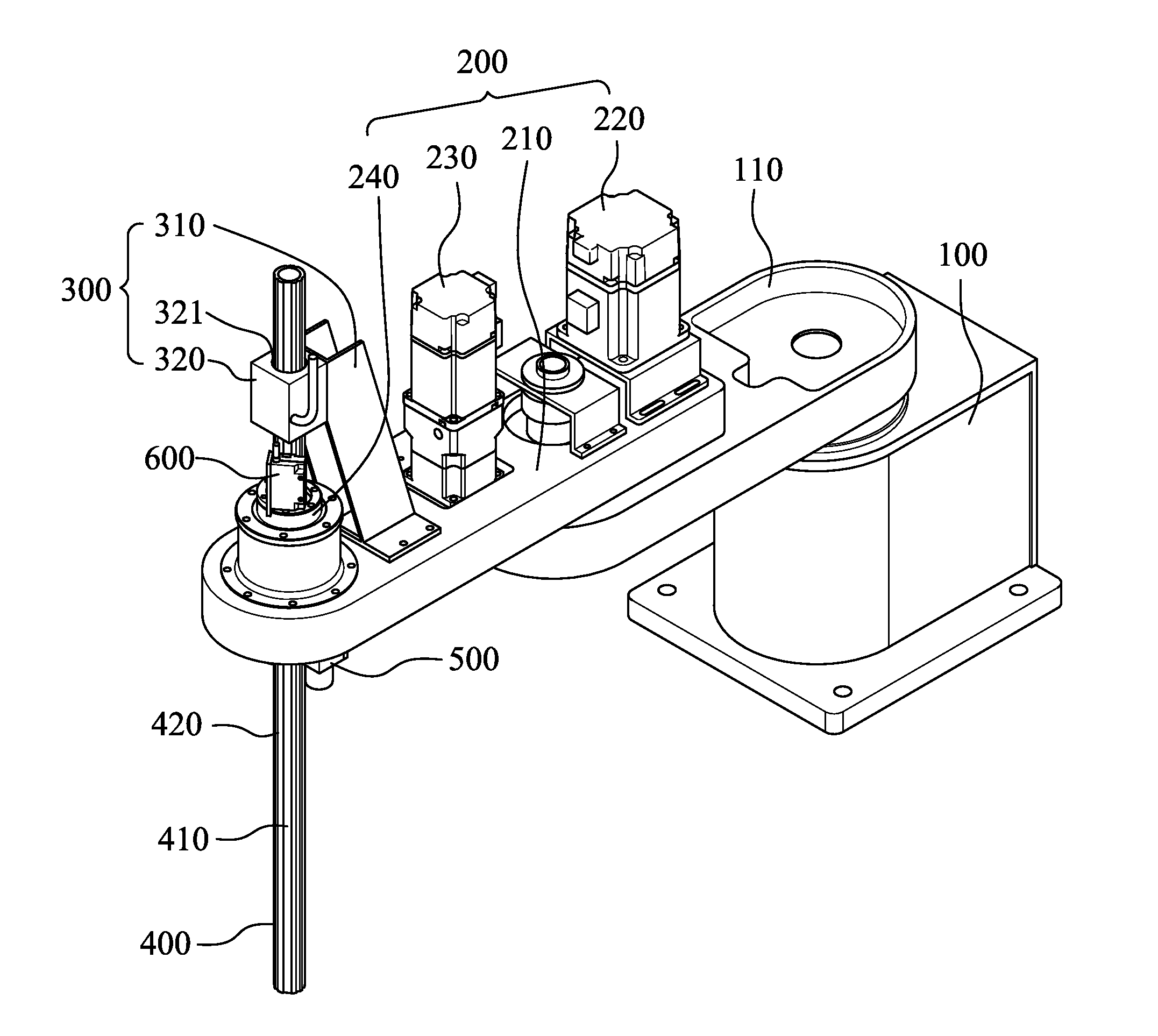
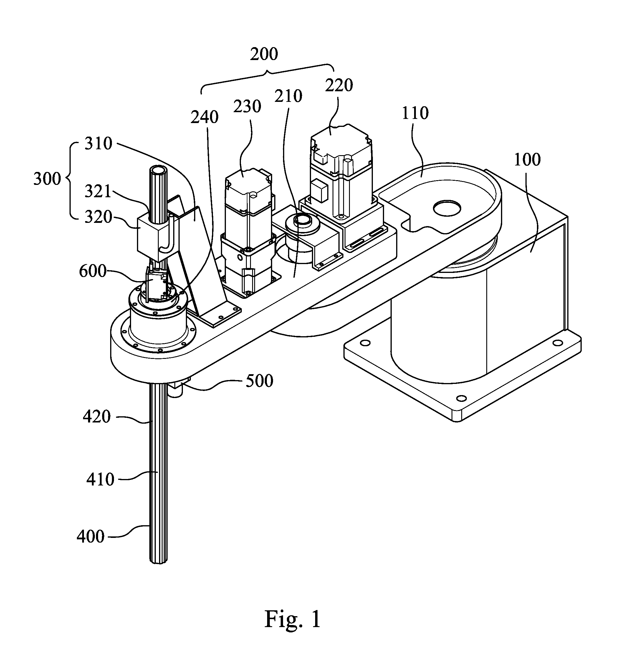
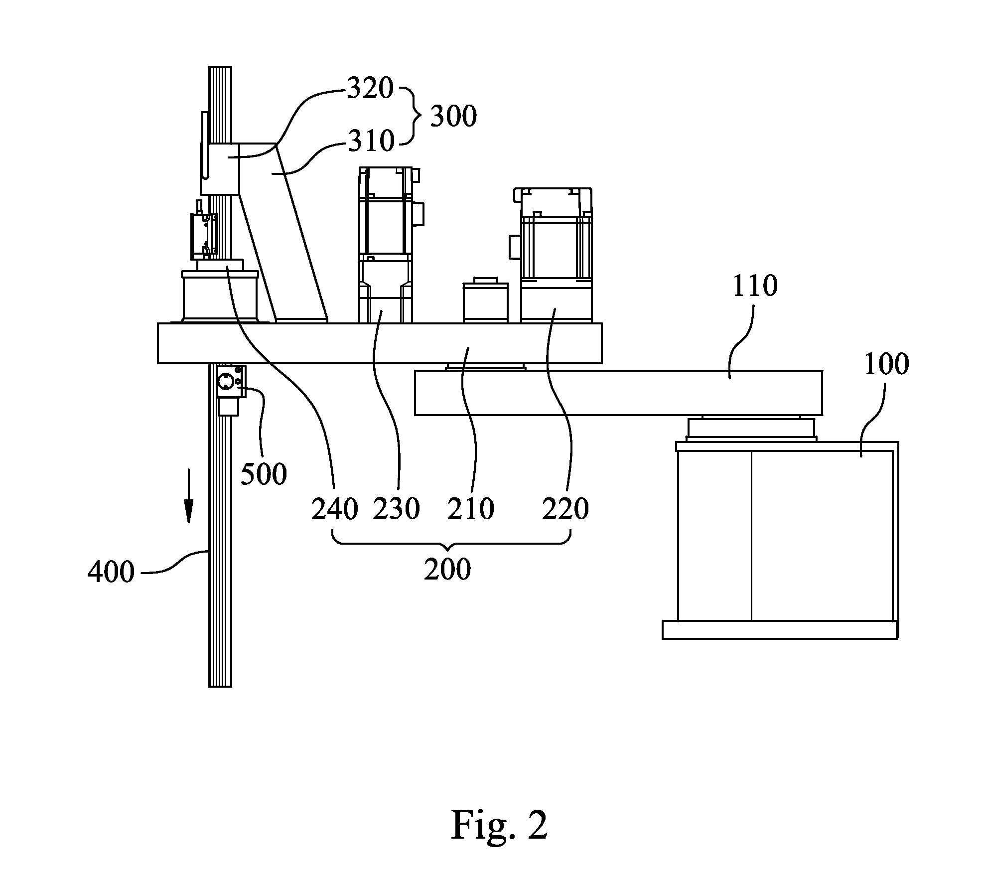
[0029]Referring to FIG. 1 to FIG. 5, FIG. 1 is a three-dimensional view of a SCARA robot according to an embodiment of the present disclosure; FIG. 2 is a side view showing a lowering state of a vertical magnetic axis 400 of the SCARA robot of FIG. 1; FIG. 3 is a side view showing a raising state of the vertical magnetic axis 400 of the SCARA robot of FIG. 1; FIG. 4 is a partial sectional view of a driving apparatus of the SCARA robot of FIG. 1; and FIG. 5 is a plan schematic view showing the vertical magnetic axis 400 driven by a rotating shaft 240 of the driving apparatus of the SCARA robot of FIG. 1.

[0030]The driving apparatus of the SCARA robot according to an embodiment of the present disclosure includes a base 100, an articulated rotating arm 110, a horizontal rotating arm 200, a linear motor coil 300, a vertical magnetic axis 400, an anti-falling device 500 and an optical counter 600. The articulated rotating arm 110 and the horizontal rotating arm 200 are connected horizonta...


PUM


Abstract

An apparatus for driving a SCARA robot is provided. The apparatus includes a body, a horizontal rotating arm, a linear motor coil and a vertical magnetic axis. The linear motor coil is disposed on the horizontal rotating arm, and the vertical magnetic axis is passed through the linear motor coil. Wherein, the vertical magnetic axis can be driven by the linear motor coil of the horizontal rotating arm by a non-contact magnetic force.

Description

RELATED APPLICATIONS[0001]The application claims priority to Taiwan Application Serial Number 101149498, filed on Dec. 24, 2012, which is herein incorporated by reference.BACKGROUND[0002]1 Technical Field[0003]The present disclosure relates to an apparatus for driving a robot and diving method thereof, more particularly, the present disclosure relates to an apparatus for driving a SCARA robot and driving method thereof.[0004]2. Description of Related Art[0005]Conventional SCARA (Selective Compliance Articulated Robot Arm) robot performs a rotational displacement on a horizontal plan by a horizontal rotating arm disposed on a base, or by multiple-linked horizontal rotating arms disposed on the base so as to perform more complicated actions. A vertical working axis is usually attached to an end of the horizontal rotating arm of the aforementioned SCARA robot, and the vertical working axis usually conducts a vertical raising / lowering action and a rotating action.[0006]The working axis ...

Claims


Application Information

Patent Timeline
IPC IPC(8): B25J9/04B25J9/12B25J18/04
CPCB25J9/044Y10T74/20317B25J9/126B25J19/021B25J19/0004H02K41/02H02K7/102B25J9/042B25J9/123B25J13/08H02K41/0354H02K41/0356
Inventor PENG, CHIH-CHENGWANG, TSAO-HSIANGWU, HSIN-HSIEN
Owner DELTA ELECTRONICS INC
Learn More