Supercharge Your Innovation With Domain-Expert AI Agents!

Cutting apparatus

a cutting machine and cutting technology, applied in the field of cutting machines, to achieve the effect of high productivity, constructionally simple and cheap

Inactive Publication Date: 2014-06-26
MANZ ITAL
View PDF6 Cites 32 Cited by
  • Summary
  • Abstract
  • Description
  • Claims
  • Application Information

AI Technical Summary

Benefits of technology

The patent describes a cutting apparatus that can cut flat elements that move continuously. It can also cut specific zones around the edges of these elements. This apparatus is highly productive and can make precise cuts on the edges of electrochemical cells used in batteries. It is also simple and cheap to build. The advantage is that it allows for the efficient and accurate cutting of cells used in batteries.

Problems solved by technology

One of the problems of the prior art is to reach a valid compromise between quality and productivity when performing the operation of cutting the cells.

Method used


Image

  • Cutting apparatus
  • Cutting apparatus
  • Cutting apparatus

Examples


Embodiment Construction

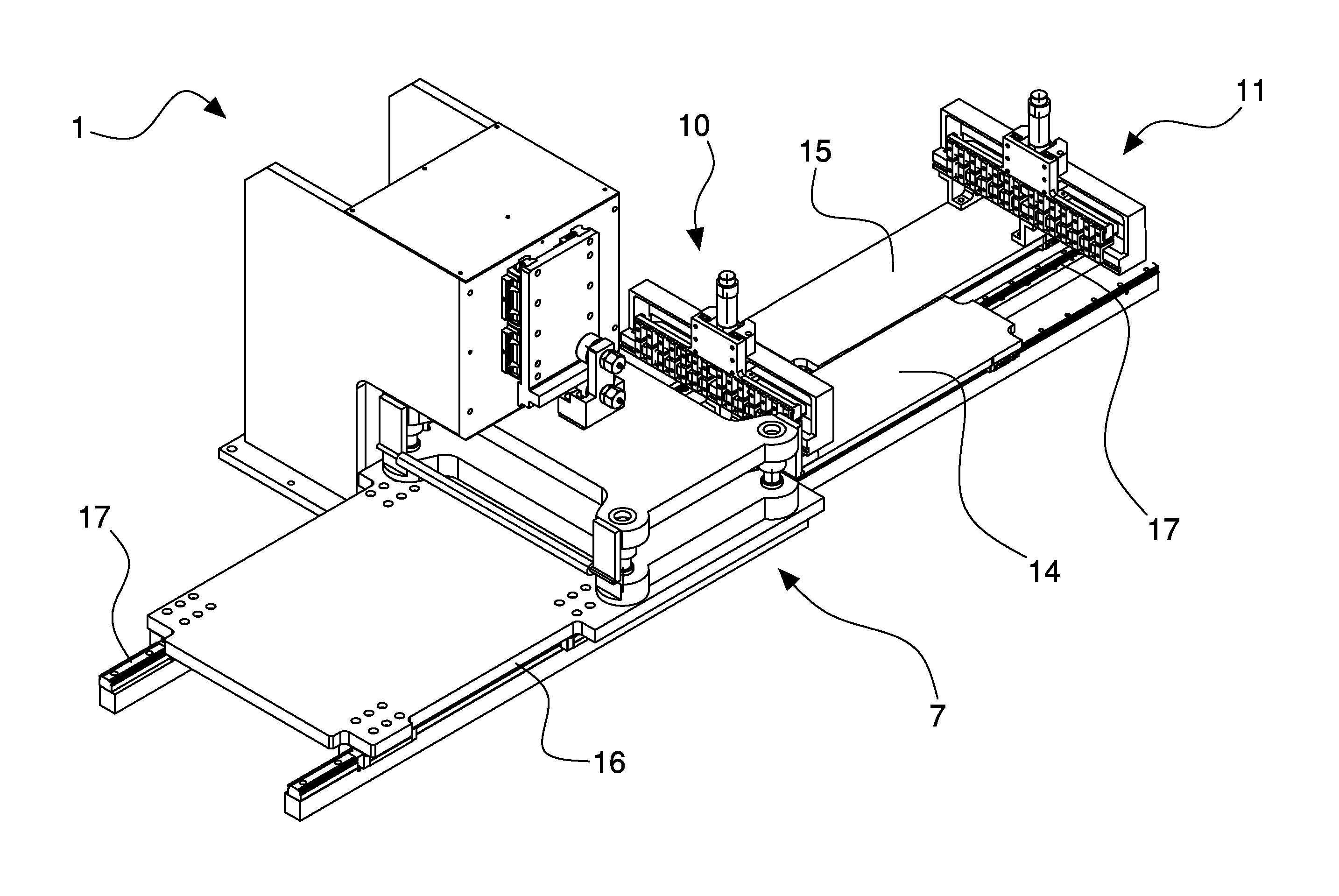
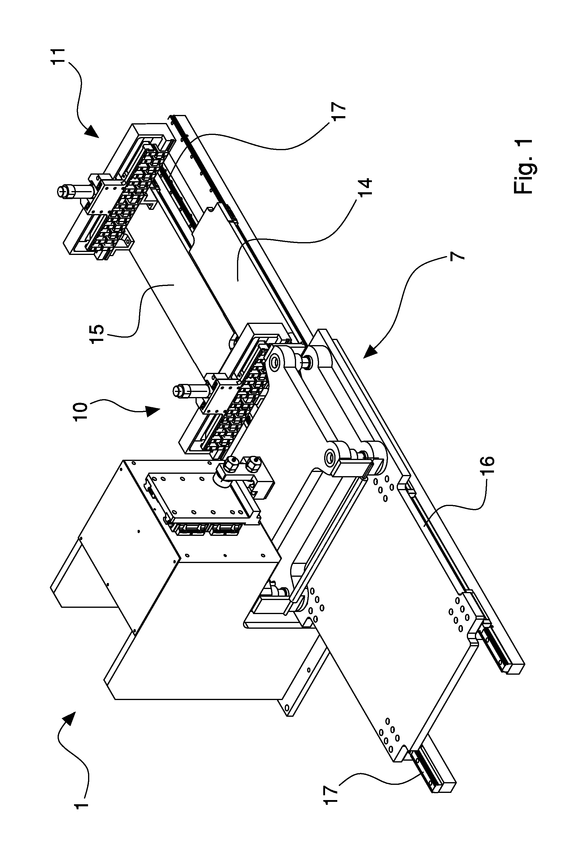
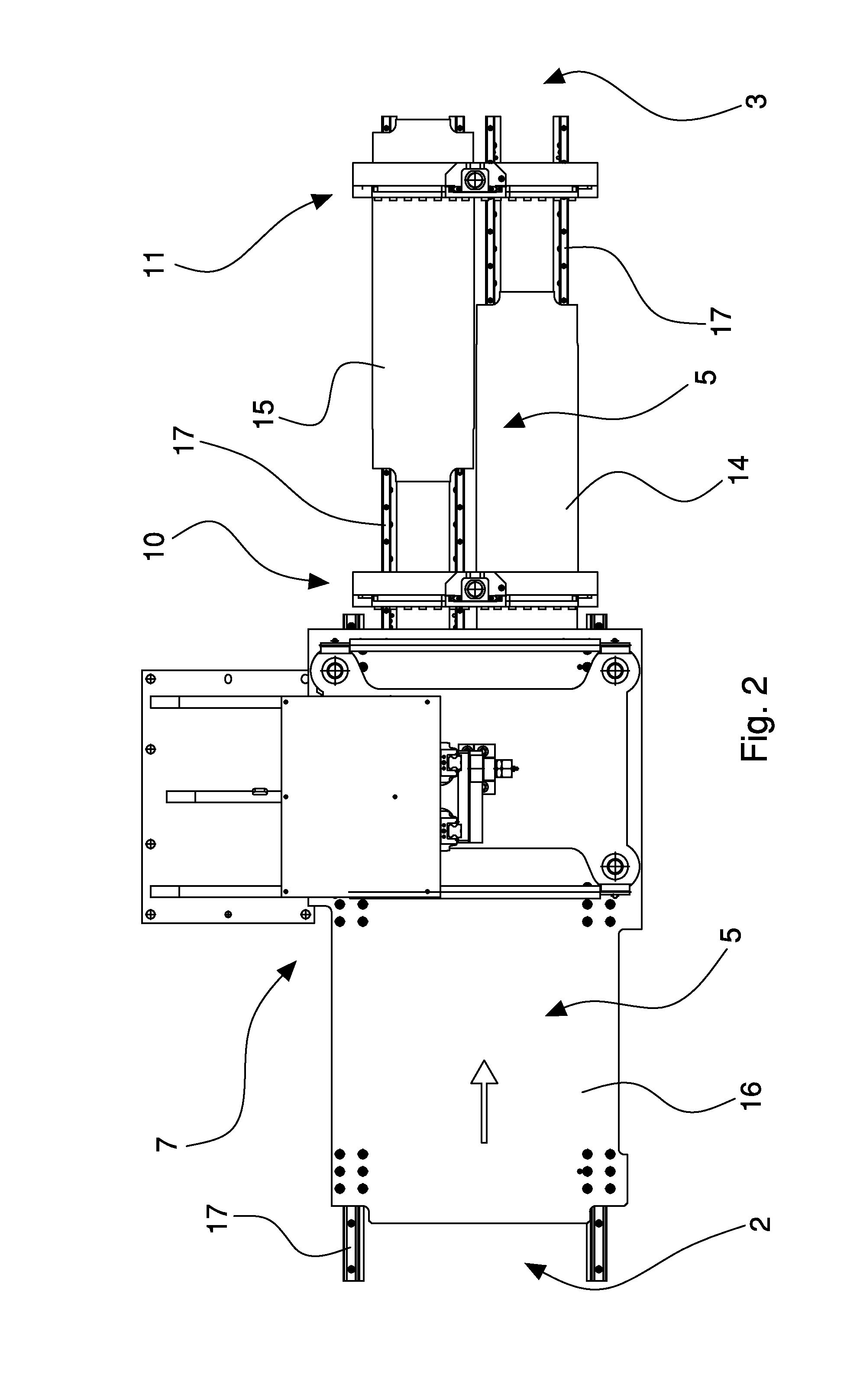
[0022]With reference to the aforesaid figures, with 1 a cutting apparatus has been indicated overall, in particular for cutting a continuous and flat element (for example in the form of a ribbon) that advances with a continuous advancing motion. In the specific case the cutting apparatus 1 is configured for cutting a part of the outline of electrochemical cells (for example for lithium batteries) arranged in a row for forming a continuous element. In particular, the cutting apparatus may be used to cut the terminals of the electrochemical cells, which will form the electrical contacts of the assembled battery.

[0023]The cutting apparatus 1 may operate, as in the specific case, for cutting preset zones of the continuous element (for example the terminals of electrochemical cells arranged in a row on the continuous element) in such a manner that the continuity of this element is preserved.

[0024]The cutting apparatus 1 may be part of a machine for producing electrochemical cells for for...


PUM

PropertyMeasurementUnit
speedaaaaaaaaaa
lengthaaaaaaaaaa
constant speedaaaaaaaaaa

Abstract

In a cutting apparatus, a continuous element with a row of electrochemical cells for lithium batteries is supplied along a supply path on which there are sequentially arranged, a cutting device and two dragging devices, each having a shuttle element that has an operating unit associated with the continuous element.

Description

BACKGROUND OF THE INVENTION[0001]The invention relates to a cutting apparatus, in particular for cutting flat elements.[0002]In particular, reference is made to a cutting apparatus that may be suitable for cutting, in preset positions, a continuous flat element, for example in the form of a continuous ribbon or film unwound from a reel.[0003]Specifically, but not exclusively, the invention may be used for cutting part of the outline of flat elements (electrodes) that are usable for producing packs of electrochemical cells for forming batteries (for example, lithium batteries).[0004]A cutting apparatus is known in which a continuous element, comprising a row of electrochemical cells with flat electrodes, is supplied with intermittent motion to a cutting device, provided with a punch and die that open and close intermittently with cutting motion coordinated with the intermittent advancing motion of the continuous element, to form the terminals that give rise to the electrical contacts...

Claims


Application Information

Patent Timeline
Patent Type & Authority Applications(United States)
IPC IPC(8): B26D1/60B26D5/02B26D5/20
CPCB26D1/60B26D5/20B26D5/02B26D1/605B26F1/40B65H20/16B65H2403/55B65H2405/52B26D7/015B65H2220/09Y10T83/4763Y10T83/0515Y10T83/4757
Inventor SALE, MASSIMILIANO
Owner MANZ ITAL
Features
  • R&D
  • Intellectual Property
  • Life Sciences
  • Materials
  • Tech Scout
  • Unparalleled Data Quality
  • Higher Quality Content
  • 60% Fewer Hallucinations
Learn More