Keyswitch structure and balance link thereof

Active Publication Date: 2014-06-26
DARFON ELECTRONICS (SUZHOU) CO LTD +1
View PDF8 Cites 8 Cited by
  • Summary
  • Abstract
  • Description
  • Claims
  • Application Information

AI Technical Summary

Benefits of technology

[0009]Another objective of the invention is to provide a keyswitch structure, which uses a limitation structure to limit a lifting range of the lift mechanism so as to improve the movement stability of the lift mechanism and further improve the up-and-down movement steadiness of the keycap. The keyswitch structure has a base plate, a keycap, a limitation structure, and a lift mechanism. The keycap is disposed above the base plate. The limitation structure is disposed on the base plate. The lift mechanism includes two supports. Each of the two supports is rotatably connected to and between the base plate and the keycap such that the keycap is capable of moving up and down relative to the base plate through the two supports. The support includes a protrusion capable of been blocked by the limitation structure for controlling an angle of rotating of the support relative to the base plate. Thereby, the lift mechanism can move within a specific up-and-down movement range not by a structural constraint produced by the connection of the lift mechanism with the keycap and the base plate, which is conducive to improvement in the movement stabil

Problems solved by technology

If the movement of the lift mechanism itself is poor, the keycap can hardly move stably.
Furthermore, if the length of the keycap such as space key is longer, a single lift mechanism cannot provide enough balance resilient force to the keycap leading to a slant easily when the keycap is pressed.
Because of the structural feature and the disposition of the lift mechanism and other components such as elastic domes (used for providing resilient force and triggering a switch) at the central por

Method used


Image

  • Keyswitch structure and balance link thereof
  • Keyswitch structure and balance link thereof
  • Keyswitch structure and balance link thereof

Examples


Embodiment Construction

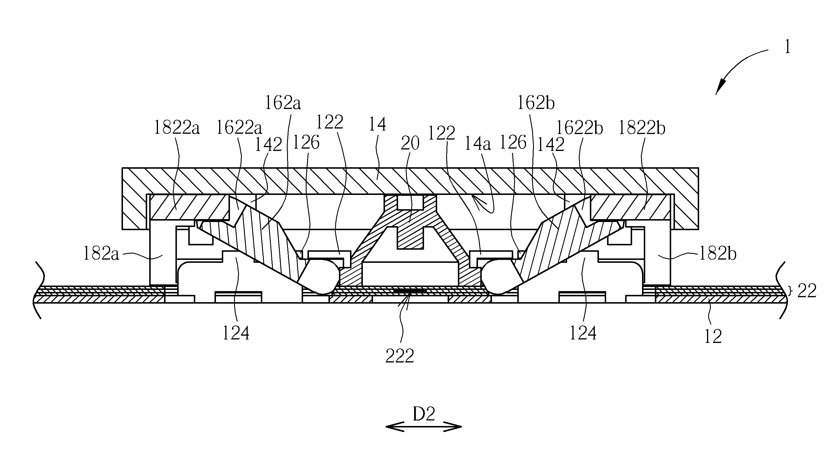
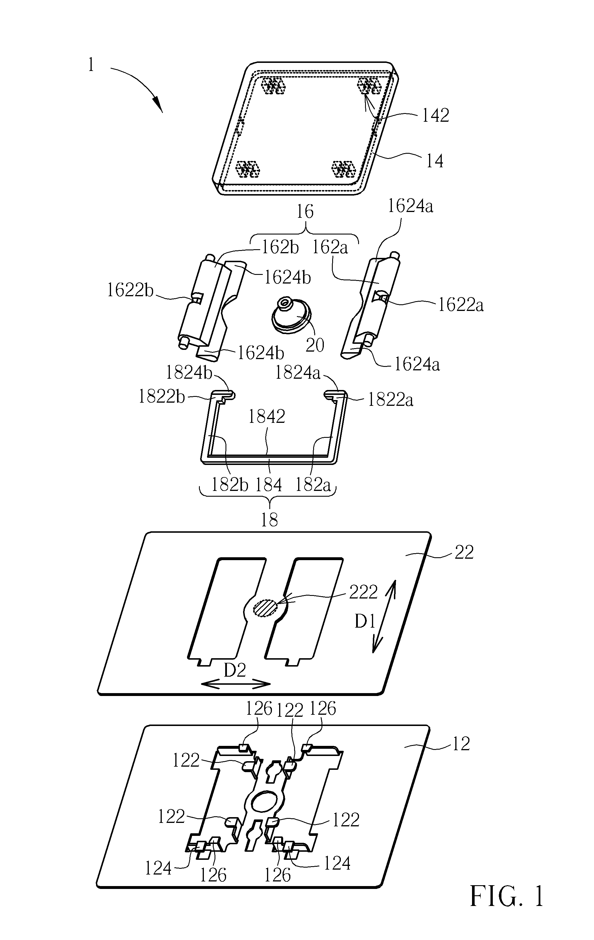
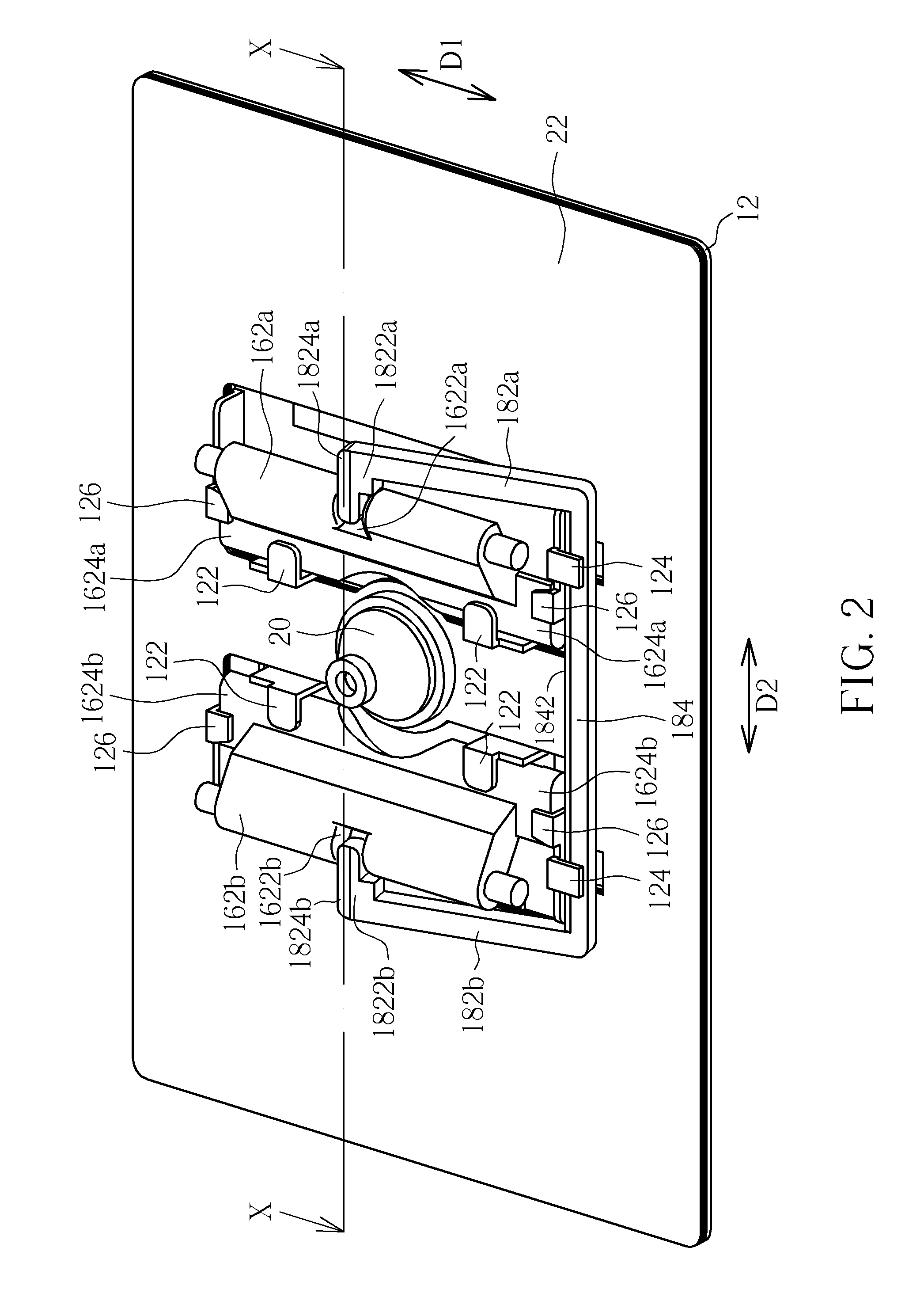
[0021]Please refer to FIGS. 1 through 3. FIG. 1 is an exploded view of a keyswitch structure 1 of an embodiment according to the invention. FIG. 2 is an assembly drawing of the keyswitch structure 1. FIG. 3 is a sectional view of the keyswitch structure 1 along the line X-X in FIG. 2. The keyswitch structure 1 includes a base plate 12, a keycap 14, a lift mechanism 16, a balance link 18, an elastic dome 20, and a membrane circuit board 22. Therein, in FIG. 2, for clear illustration of the keyswitch structure 1 after assembled, the keycap 14 is not shown. The keycap 14 is disposed above the base plate 12. The lift mechanism 16 is disposed between the base plate 12 and the keycap 14 and connected to engagement structures 122 of the base plate 12 and engagement structures 142 (shown in dashed lines in FIG. 1) on a bottom surface 14a of the keycap 14, such that the keycap 14 is capable of moving up and down relative to the base plate 12 through the lift mechanism 16. The lift mechanism ...


PUM


Abstract

A keyswitch structure includes a base plate, a keycap, a lift mechanism, and a balance link. The lift mechanism connects between the keycap and the base plate such that the keycap can move up and down relative to the base plate. The balance link is formed substantially in a U-shaped profile. The middle portion thereof is rotatably disposed on the base plate; the two ends thereof are respectively formed in an L-shaped profile and rotatably inserted into two slot structures on the keycap or the lift mechanism or both. Compared with a conventional balance link formed in an n-shaped profile connecting a keycap and a base plate, the invention provides more diverse structural connections, conducive to structural miniaturization. Furthermore, a support of the lift mechanism includes a protrusion capable of being blocked by a limitation structure disposed on the base plate for controlling the rotation angle of the support.

Description

BACKGROUND OF THE INVENTION[0001]1. Field of the Invention[0002]The invention relates to a keyswitch structure, and especially relates to a keyswitch structure having a balance link and a balance link for a keyswitch structure.[0003]2. Description of the Prior Art[0004]The structure of conventional mechanical keyswitches is a keycap and a base plate with a lift mechanism therebetween such that the keycap is capable of moving up and down relative to the base plate. The movement stability, including movement stroke and even steadiness, of the keycap usually depends on the lift mechanism. If the movement of the lift mechanism itself is poor, the keycap can hardly move stably. Furthermore, if the length of the keycap such as space key is longer, a single lift mechanism cannot provide enough balance resilient force to the keycap leading to a slant easily when the keycap is pressed. Hence, in practice, the keycap with a longer length is usually provided with a plurality of lift mechanisms...

Claims


Application Information

Patent Timeline
IPC IPC(8): H01H3/12
CPCH01H3/122H01H13/7065H01H2237/00
Inventor HSU, CHIEN-SHIH
Owner DARFON ELECTRONICS (SUZHOU) CO LTD
Why Eureka
Try Eureka