Variable flow self-diluting feedwell system

a self-diluting, feedwell technology, applied in sedimentation settling tanks, separation processes, filtration separation, etc., can solve the problems of turbulence in the tank and compromise the solids settling ra

Inactive Publication Date: 2014-06-26
F L SMIDTH & CO AS
View PDF10 Cites 10 Cited by
  • Summary
  • Abstract
  • Description
  • Claims
  • Application Information

AI Technical Summary

Benefits of technology

[0009]Another specific object of the present invention is to provide such a feed slurry dilution system and / or associated method which is easy and inexpensive to implement.
[0010]A related object of the present invention is to provide such a feed slurry dilution system and / or associated method which is easy and inexpensive to implement as a retrofit to feedwell assemblies of existing and operating thickener / clarifier / settling tanks.
[0022]It is to be noted that if a duckbill type variable-orifice nozzle is oriented with the elongate orifice dimension extending across the mixing conduit or channel, the influent slurry flow stream or slurry infeed stream is non-circular and flatter and thus broader across the width of the channel instead of a tubular stream flowing down the center of the mixing channel. This flattened slurry infeed stream is more conducive to mixing the solids and dilution fluids together in an area closer to the dilution-liquid suction or eduction inlet of the mixing channel and that the flows are better mixed prior to the exit from the mixing channel, hence producing a more uniform solids concentration over the entire open channel as it enters the feedwell.
[0025]A feedwell feed slurry dilution system provided with a variable orifice nozzle in accordance with the present invention helps keep an open channel system scoured and cleaned and allows for a variable incoming flow rate volume while the valve keeps the nozzle velocity more or less constant as the valve clamps down a bit as the flow rate decreases. This is of particular benefit in generally rectangular open-channel type mixing conduits where the invention results not only in a more even or uniform mixing of diluting liquid in the slurry stream entering the feedwell from the mixing conduit, but also serves to prevent a buildup of particles along the lower corners of the mixing conduit.

Problems solved by technology

In other words, introduction into a thickener / clarifier of an influent feed stream under high fluid velocity tends to cause turbulence in the tank and compromises the settling rate of solids.

Method used


Image

  • Variable flow self-diluting feedwell system
  • Variable flow self-diluting feedwell system
  • Variable flow self-diluting feedwell system

Examples


Embodiment Construction

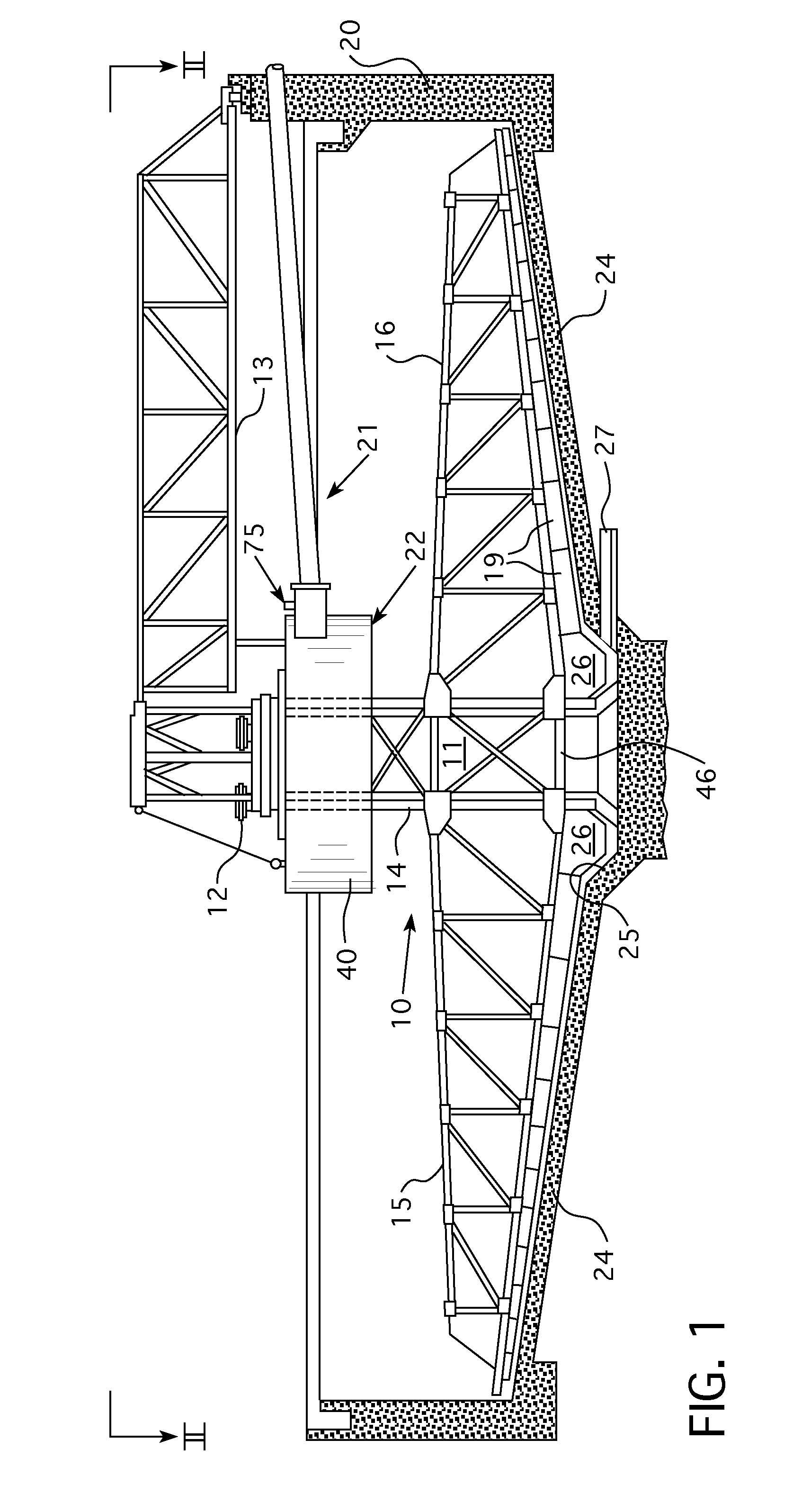
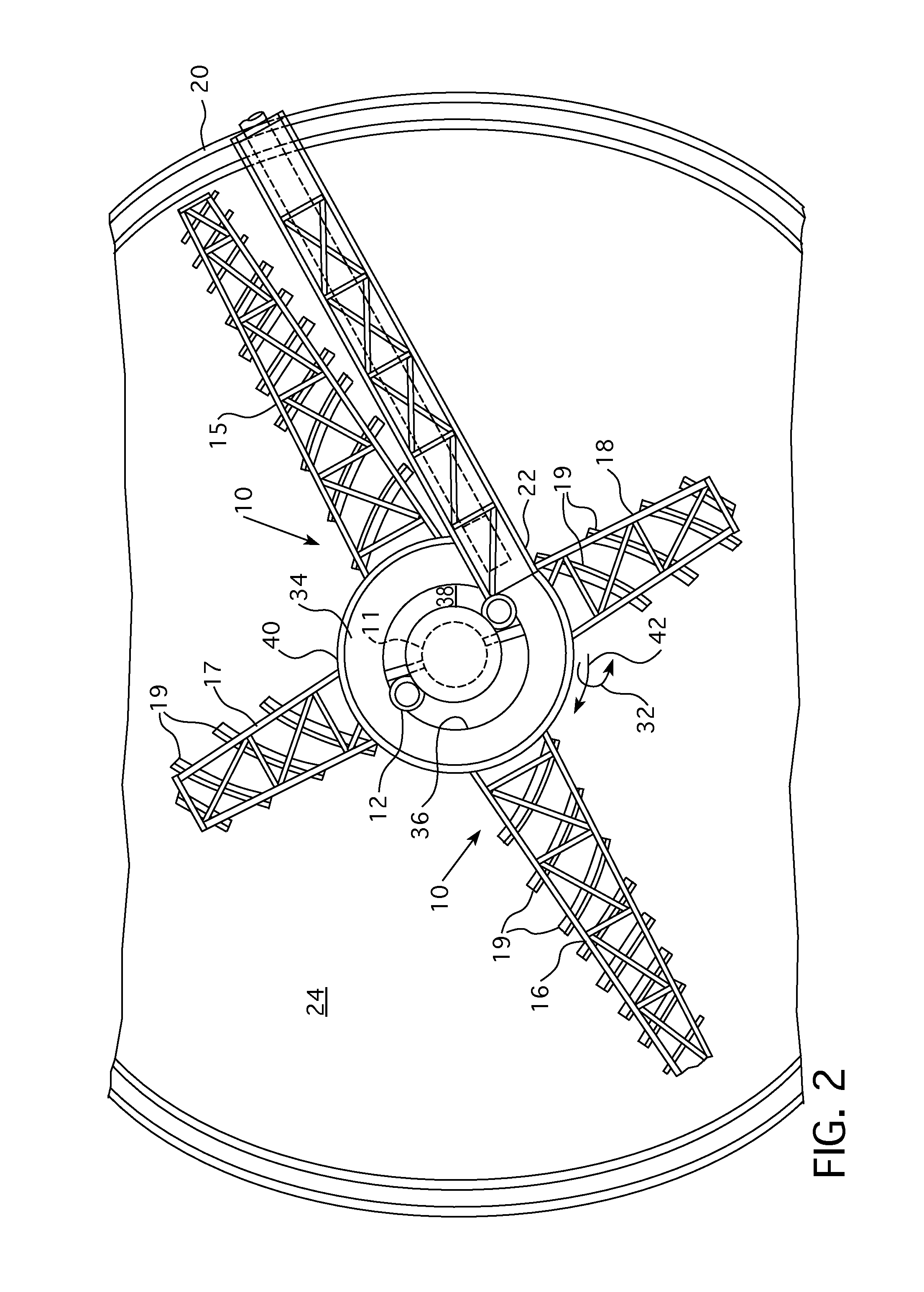
[0035]As illustrated in FIGS. 1 and 2, a thickener / clarifier comprises a continuously operating thickening / settling tank 20 wherein a sludge raking structure 10 is supported for rotation upon a center pier 11. A drive mechanism 12 of any suitable known construction is mounted atop the pier providing the driving torque for the rake structure. The pier also supports the inner end of an access bridge 13.

[0036]Rake structure 10 comprises a central vertical cage portion or cage 14 surrounding the pier 11, and rake arms of girder like construction extending rigidly from the cage. Rake structure 10 has one pair of long rake arms 15 and 16 opposite to one another, and a pair of short rake arms 17 and 18 disposed at right angles thereto, all arms having sludge impelling or conveying blades 19 fixed to the underside thereof.

[0037]Rake structure 10 operates in a settling tank 20 to which a feed suspension or feed pulp is supplied through a feed dilution system 21 terminating in a cylindrical f...


PUM

PropertyMeasurementUnit
constant velocityaaaaaaaaaa
flexibleaaaaaaaaaa
velocityaaaaaaaaaa

Abstract

In a feed dilution system and method for a thickener or settling tank, a feed pipe nozzle has a variable orifice configured to provide an infeed slurry flow stream of substantially constant velocity. The feed pipe orifice is disposed in a mixing conduit proximate an upstream end thereof, while a downstream end of the mixing conduit is functionally attached to a feedwell inside the thickener or settling tank, so that the mixing conduit communicates with the feedwell. Where a diluting liquid is introduced into the mixing conduit, the variable-orifice nozzle ensures a substantially uniform degree of dilution of the influent slurry feed stream by the diluting liquid.

Description

BACKGROUND OF THE INVENTION[0001]This invention relates to thickener / clarifier settling tanks used to separate liquid and solid components of an influent feed slurry and specifically relates to feedwell apparatus employed in such thickener / clarifiers to enhance the clarification process. More specifically, the invention relates to a feed dilution system and method that delivers a diluted solids slurry to a feedwell of a thickener or clarifier tank.[0002]Thickener / clarifier tanks are used in a wide variety of industries to separate influent feed slurry comprising a solids, or particulate, containing fluid to produce a “clarified” liquid phase having a lower concentration of solids than the influent feed slurry and an underflow stream having a higher concentration of solids than the influent feed slurry. Thickener / clarifier tanks conventionally comprise a tank having a floor and a continuous wall, which define a volume within which the clarification process takes place. Thickener / clar...

Claims


Application Information

Patent Timeline
Patent Type & Authority Applications(United States)
IPC IPC(8): B01D21/24B01D21/01
CPCB01D21/01B01D21/2405B01D21/08B01D21/2427B01D21/307B01D21/34
Inventor LAROS, TIMOTHY J.
Owner F L SMIDTH & CO AS
Why Eureka
Try Eureka