
LED lighting apparatus with improved total harmonic distortion in source current

a technology of source current and total harmonic distortion, which is applied in the direction of electroluminescent light sources, battery data exchange, electric lighting sources, etc., can solve the problems of increasing the manufacturing cost the restriction of the use the complexity of the circuit of the light emitting device, so as to improve the total harmonic distortion of the input current, improve the luminous intensity uniformity and brightness, and increase the power factor

Inactive Publication Date: 2014-06-26
POSCO LED
View PDF0 Cites 16 Cited by
  • Summary
  • Abstract
  • Description
  • Claims
  • Application Information

AI Technical Summary

Benefits of technology

This solution enhances the power factor by reducing THD, achieves uniform luminous intensity, and extends the lifespan of LED arrays by ensuring consistent light emission across all groups, thereby simplifying the circuit configuration and reducing manufacturing costs.

Problems solved by technology

Therefore, a light emitting device using the light emitting element is restrictive in use and must include a separate circuit, such as SMPS, so as to use an AC voltage that has been used at home.
Consequently, the circuit of the light emitting device becomes complicated and the manufacturing cost of the light emitting device increases.
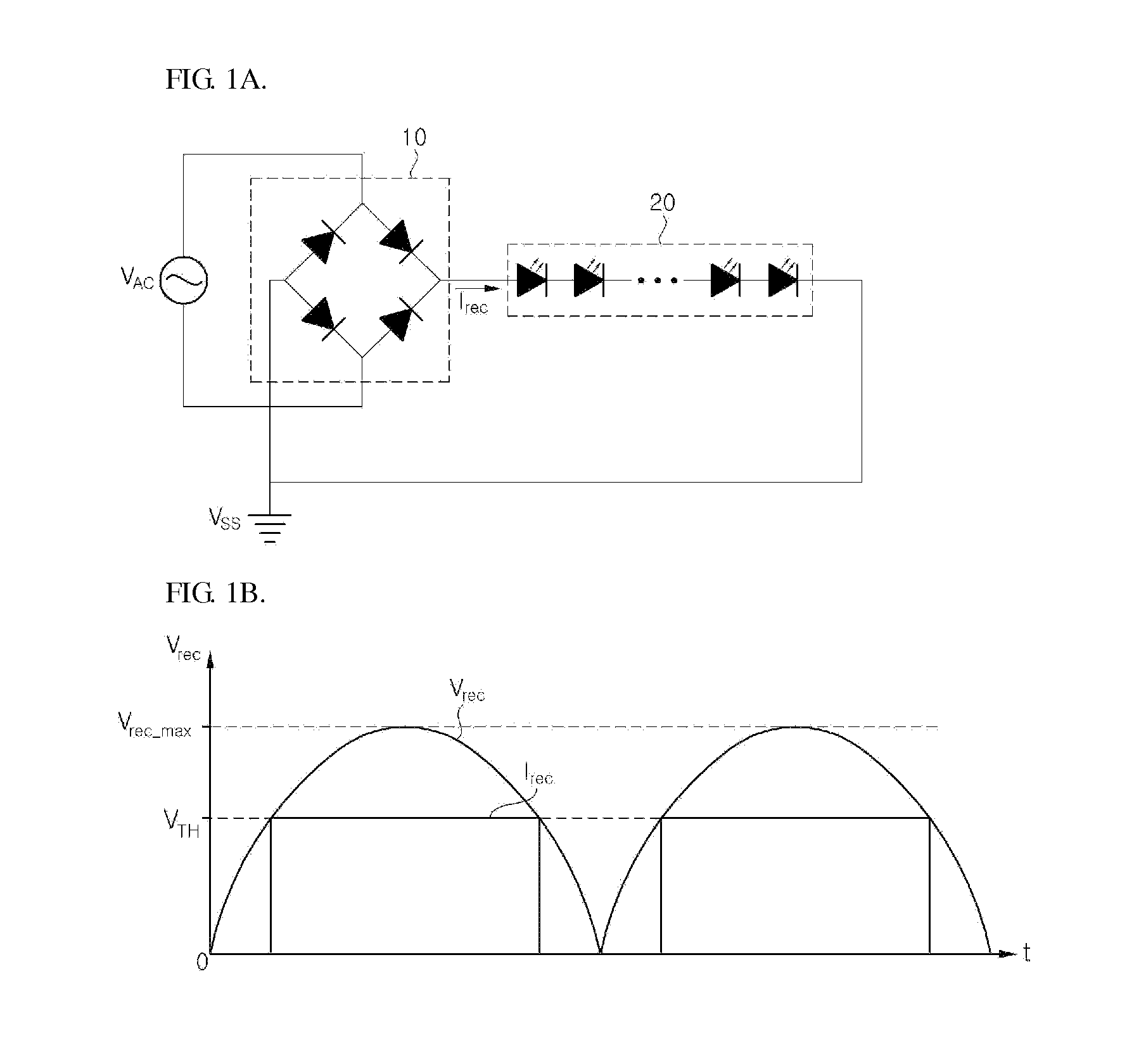
Therefore, a power factor is deteriorated.
However, in this case, the size of the LED lighting apparatus increases, and the manufacturing cost of the LED lighting apparatus rises.
Also, the circuit configuration of the LED lighting apparatus becomes complicated.
However, in the case of the LED lighting apparatus using the conventional sequential driving scheme, since the light emission periods of the plurality of LED arrays are different, the luminous intensity uniformity of the LED lighting apparatus is degraded and the lifespan of the LED arrays becomes disproportionate.
Therefore, the lifespan of the LED lighting apparatus is subjected to the LED array having a relatively long emission time.

Method used


Image

  • LED lighting apparatus with improved total harmonic distortion in source current
  • LED lighting apparatus with improved total harmonic distortion in source current
  • LED lighting apparatus with improved total harmonic distortion in source current

Examples


Embodiment Construction

[0037]Specific embodiments of the present invention will be described below in detail with reference to the accompanying drawings. These embodiments will be fully described in such a manner that those skilled in the art can easily carry out the present invention. It should be understood that various embodiments of the present invention are different from one another, but need not be mutually exclusive. For example, specific shapes, structures and characteristics described herein can be implemented in other embodiments, without departing from the spirit and scope of the present invention. In addition, it should be understood that the positions and arrangements of the individual elements within the disclosed embodiments can be modified without departing from the spirit and scope of the present invention. Therefore, the following detailed description is not intended to be restrictive. If appropriately described, the scope of the present invention is limited only by the accompanying cla...


PUM


Abstract

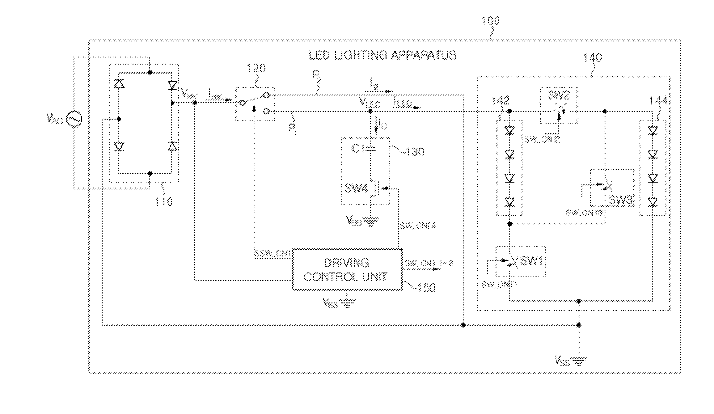
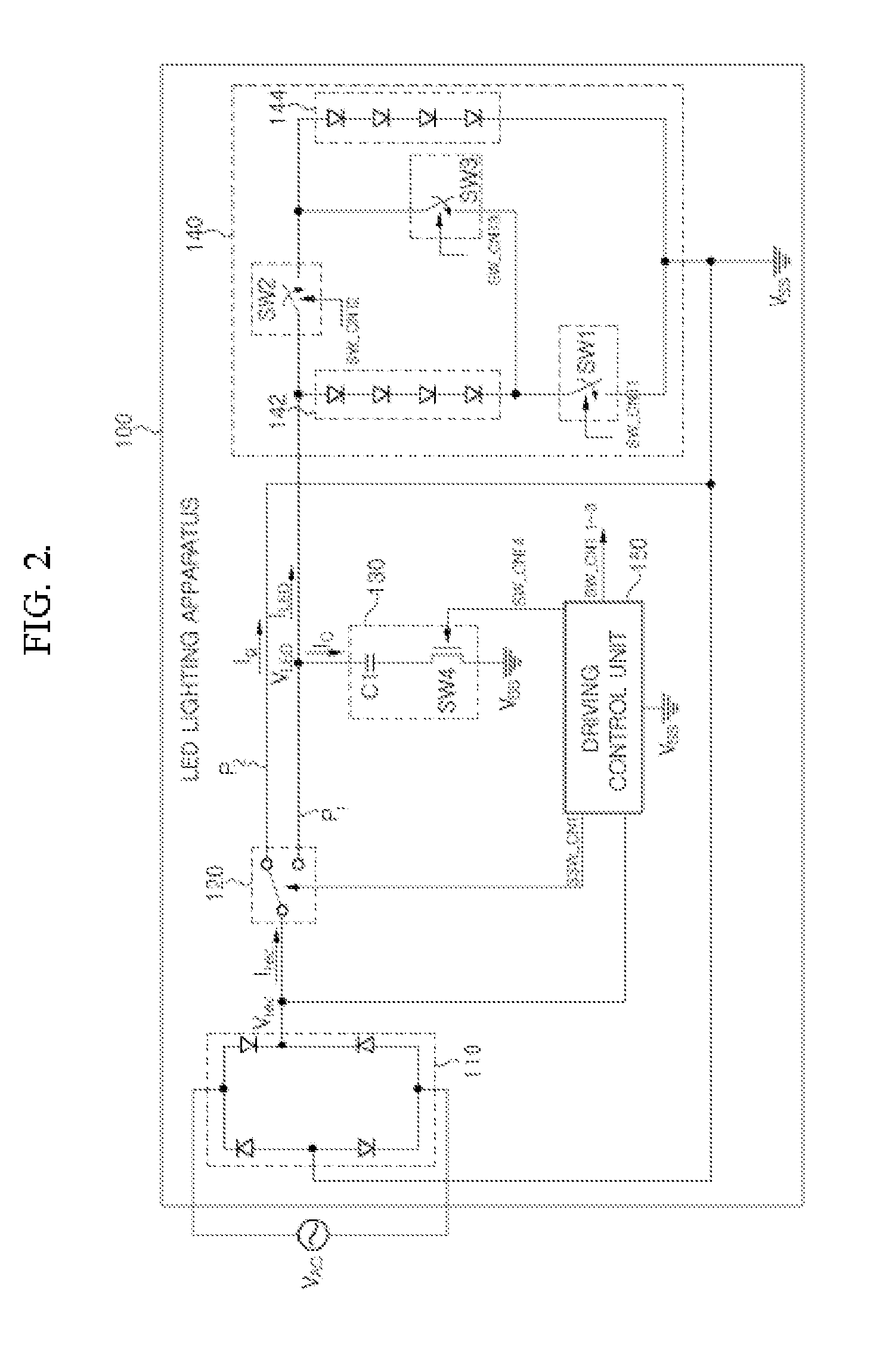
The LED lighting apparatus includes: a rectification block; an LED block including a first light emitting group and a second light emitting group; a charging / discharging block configured to charge electric charges in a charging period, and discharge electric charges in a discharging period; a driving control unit configured to determine a voltage level of a rectified voltage, controls a path selection switch to connect the rectification block to the LED block and controls the charging / discharging block to charge electric charges in the charging period, and controls the path selection switch to connect the rectification block to a ground and controls the charging / discharging block to discharge electric charges from the charging / discharging block to the LED block in the discharging period; and a path selection switch configured to connect the rectification block to the LED block in the charging period, and connect the rectification block to the ground in the discharging period.

Description

CROSS-REFERENCE TO RELATED APPLICATION[0001]This application claims priority of Korean Patent Application No. 10-2012-0150881, filed on Dec. 21, 2012, in the Korean Intellectual Property Office, which is hereby incorporated by reference in its entirety.BACKGROUND OF THE INVENTION[0002]1. Field of the Invention[0003]The present invention relates to an LED lighting apparatus with improved harmonic distortion components of a source current, and more particularly, to an LED lighting apparatus, which increases a power factor by improving a total harmonic is distortion (THD) of an input current in such a manner that a waveform of the input current output from a rectification block is made maximally close to a sine wave by using a path selection switch and a charging / discharging block, and improves the lifespan and luminous intensity uniformity of LED elements by actively changing a series / parallel connection relationship among a plurality of LED groups according to a voltage level of a re...

Claims


Application Information

Patent Timeline
Patent Type & Authority Applications(United States)
IPC IPC(8): H05B33/08H05B44/00
CPCH05B33/0842H05B45/44H05B45/30H05B45/3725H05B45/48H05B45/37H02J7/00043
Inventor YOON, SEONG BOKKIM, DAE WONKIM, JUNG HWA
Owner POSCO LED
Learn More