Sealed rolling bearing

a rolling bearing and seal technology, applied in the direction of rolling contact bearings, shafts and bearings, rotary bearings, etc., can solve the problems of reducing the service life of the bearing, difficult in many cases to enhance the seal performance sufficiently, etc., to reduce the amount of frictional heat generation of the seal lip, improve the service life, and improve the sealing performance. , the effect of reducing the amount of frictional heat generation

Inactive Publication Date: 2014-06-26
NTN CORP
View PDF6 Cites 8 Cited by
  • Summary
  • Abstract
  • Description
  • Claims
  • Application Information

AI Technical Summary

Benefits of technology

[0016]As described above, in the sealed rolling bearing of the present invention, the ratio of the difference between the outer diameter of the seal sliding contact surface and the inner diameter of the seal lip in its natural state to the diameter of the shaft on which the inner races are fitted is set to be in the range of 0.27 to 0.40% that is not within the ordinary use parameter range, so as to decrease the amount of frictional heat generation of the seal lip and to apply adequate pressing force to the seal lip. Therefore, it is possible to secure more excellent seal performance than conventional sealed rolling bearings without increasing manufacturing costs and complicating the bearing structure.

Problems solved by technology

However, especially in a bearing for a roll neck, since the internal pressure of the bearing tends to become negative due to temperature changes of the bearing caused by the bearing being rotated on and off repeatedly, even if a sealed rolling bearing configured as described above is used as a bearing for a roll neck, water may be sucked into the bearing from outside the seal lips, thus causing service life of the bearing to be shortened.
However, it is difficult in many cases to enhance seal performance sufficiently even if the inner diameter of the seal lip is shortened so as to increase pressing force of the seal lip as described above.

Method used


Image

  • Sealed rolling bearing
  • Sealed rolling bearing
  • Sealed rolling bearing

Examples


Embodiment Construction

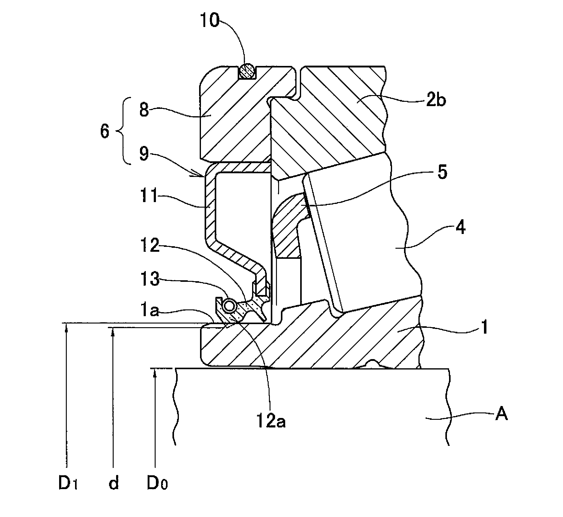
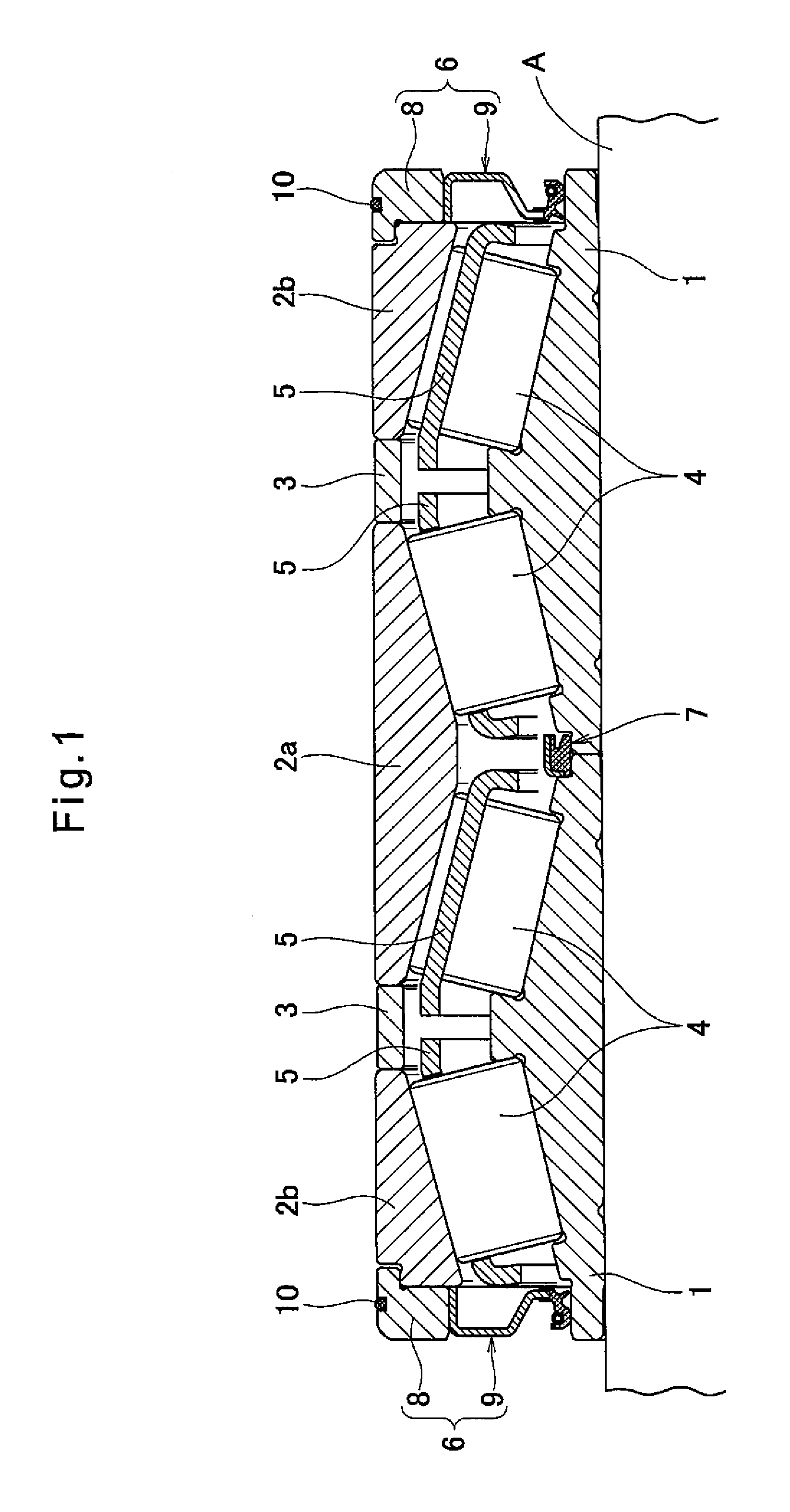
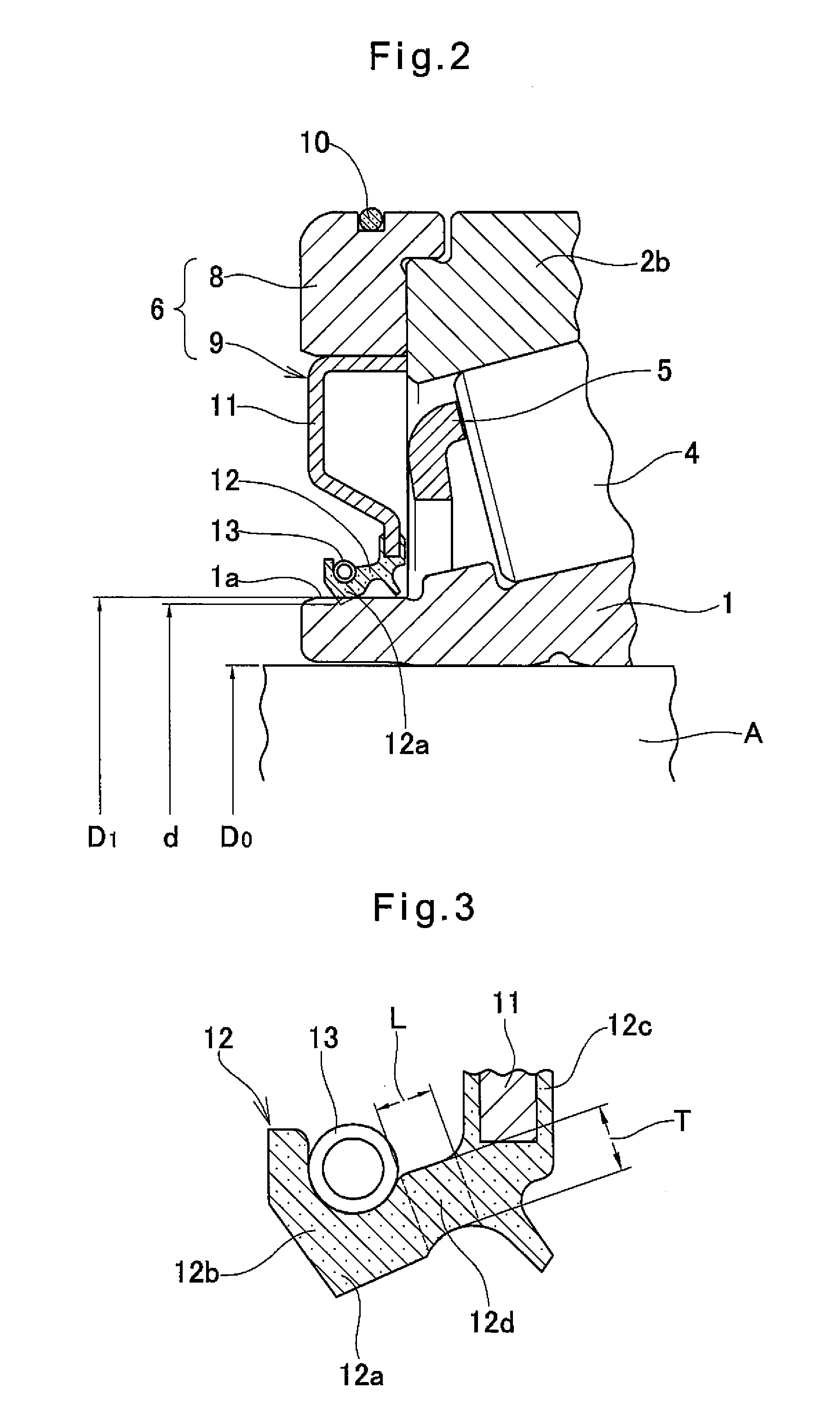
[0024]The embodiment of the present invention is now described with reference to FIGS. 1 through 5. As illustrated in FIG. 1, this sealed rolling bearing is a four-row tapered roller bearing supporting a roll neck portion (shaft) A of a steel rolling mill. The bearing includes right and left two inner races 1 each having two raceways, a central outer race 2a having two raceways, and two outer races 2b each having a raceway and arranged on both sides of the outer race 2a through spacers 3, and tapered rollers 4 arranged in four rows between the inner races 1 and the outer races 2a and 2b and retained by retainers 5. The interior space of the bearing between the inner races 1 and the outer races 2a, 2b is sealed by side seal assemblies 6 arranged at both ends of the bearing and an intermediate seal assembly 7 arranged in the center of the bearing.

[0025]The side seal assemblies 6 each include an annular seal case 8 pressed against the outer end surface of the outer race 2b, and a conta...


PUM

PropertyMeasurementUnit
outer diameteraaaaaaaaaa
inner diameteraaaaaaaaaa
diameteraaaaaaaaaa

Abstract

In a sealed rolling bearing for use in an environment where a large amount of water is splashed and the internal pressure of the bearing becomes negative, a ratio of the difference between an outer diameter of a seal sliding contact surface of an inner race and an inner diameter of a seal lip of an elastic seal member in its natural state to a diameter of a roll neck portion (shaft) on which the inner race is fitted is in the range of 0.27 to 0.40%. This provides reduced frictional heat generation of the seal lip and adequate pressing force applied to the seal lip, thus securing excellent seal performance without requiring an additional mechanism, such as a vent to a contact seal.

Description

TECHNICAL FIELD[0001]The present invention relates to a sealed rolling bearing including contact seals fixed to an outer race of the bearing and each having a seal lip pressed tightly against a seal sliding contact surface of an inner race of the bearing, thereby sealing the interior space of the bearing.BACKGROUND ART[0002]As rolling bearings (bearings for a roll neck) used to support a roll neck portion of a steel rolling mill, which are used in situations where a large amount of water such as roll cooling water or emulsion including rolling lubricating oil scattered therein is splashed, sealed rolling bearings are widely used which include contact seals fixed to an outer race of the bearing and each having a seal lip pressed tightly against a seal sliding contact surface of an inner race of the bearing. The seal lips thus seal the interior space of the bearing between the inner race and the outer race so as to prevent water from leaking into the interior space of the bearing.[000...

Claims


Application Information

Patent Timeline
Patent Type & Authority Applications(United States)
IPC IPC(8): F16C33/78F16C33/80
CPCF16C33/7813F16C33/7876F16C19/388F16C33/805F16C2322/12F16C33/7823F16C2240/70F16C33/7826F16C33/80F16C2240/40
Inventor TOYODA, TSUKASASHIMIZU, YASUHIRO
Owner NTN CORP
Why Eureka
Try Eureka