Oil duct balance type bearing

A balanced, oil channel technology, used in bearings, bearing cooling, bearing components, etc., can solve the problems of aggravating the wear of sliding friction surfaces, short service life, affecting the output efficiency and economic benefits of the power station

Pending Publication Date: 2017-05-31
郭远军
View PDF0 Cites 0 Cited by
  • Summary
  • Abstract
  • Description
  • Claims
  • Application Information

AI Technical Summary

Problems solved by technology

[0013] Since the existing cooling oil mainly adopts No. 46 turbine oil or No. 32 turbine oil, the kinematic viscosity of No. 46 turbine oil at 40°C is 45.8, and its optimal operating temperature range is 44-46°C; The kinematic viscosity at 40°C is 32, and the optimal operating temperature range is 38-40°C; the existing cooling oil needs to be controlled below 65°C during operation. When the temperature of the cooling oil is too high, the viscosity becomes smaller and will Lead to poor lubrication, larger friction coefficient, increased frictional heat generation, rapid rise in oil temperature, and high oil temperature, aggravating the wear of the sliding friction surface; existing bearings adopt this cooling structure, in order to prevent excessive oil temperature from causing wear Watt, it is necessary to monitor the oil temperature in the bearing. When the temperature is too high, it is necessary to increase the water flow of the cooling body. When the temperature is too high, an alarm is given and the operation is stopped.
[0014] Due to the low heat exchange efficiency of the existing hydraulic generator bearings, the generator is prone to alarm shutdown, which not only affects the output efficiency and economic benefits of the power station, but also affects other equipment in the power station during the shutdown and start-up process of the power station. Great impact on service life
[0015] The reason for the above problems is that the density and viscosity of the cooling oil are greatly affected by the change of oil temperature. The higher the temperature of the cooling oil, the smaller the density and viscosity. After the cooling oil is cooled by the cooling copper tube a71, The cooling oil with a larger cooling capacity sinks, and the flow rate becomes smaller, and the cooling oil with a smaller cooling capacity floats up, causing the cooling oil with a larger cooling capacity in the lower area of ​​the second oil chamber a6 to stay, while the cooling oil in the upper area The flow rate of the smaller cooling oil becomes faster and flows out from the oil outlet a62, resulting in the high temperature of the cooling oil flowing out of the oil outlet a62
[0016] In addition, the bearings in the prior art also have the following problems: 1. The oil injection groove inside the support pad is designed at the top, and the inside of the support pad needs to be scraped to form small oil storage pits to improve lubrication. Because the cooling oil in the support tile is brought from the oil injection groove to the small oil storage pit on the sliding friction surface through the rotation of the main shaft, the amount of cooling oil brought in is small, and the cooling oil exchange rate is low, resulting in heat exchange in the bottom area of ​​the support tile. The speed is small, and because the standard of scraping tiles is generally two to three contact points per square centimeter, the tile scraping process is time-consuming and labor-intensive; 2. Since the existing oil drainage holes are generally designed at one end of the supporting tile, The oil circuit at the other end of the support pad is blocked, and there is a large temperature difference between the two ends of the support pad, which easily causes the deformation of the support pad and causes the phenomenon of pad wear; 3. The cooling between the thrust pad and the thrust disc of the existing thrust bearing The oil is directly pressed in from the outer diameter side of the thrust pad through the oil pump. This method has a simple structure, but due to the obstruction of centrifugal force, it is difficult for the cooling oil to be pressed into the inner diameter side of the thrust pad, which may easily lead to high temperature on the inner diameter side of the thrust pad. ;4. After manual scraping, there is a big difference in the quality of scraping tiles. For tiles with poor quality scraping tiles, there are large distribution differences in the area of ​​contacts and the depth of oil storage points, resulting in sliding friction of the supporting tiles. There are problems of uneven oil film thickness and uneven oil film flow rate on the surface. There are high-temperature points on the sliding friction surface, which are prone to produce impurities and cause unstable friction coefficients; 5. The large parts of the bearing adopt casting technology, and the national standard casting process allows 2% defects. The service life of its components is short, which greatly affects the stability of the whole machine after installation; 6. The bearing pad mounting frame is fixed by two screws on the left and right, and radial vibration will occur when the hydroelectric generator fails, resulting in loose bearing pads , the main shaft is prone to polarization, resulting in deformation of the main shaft; 7. The bearing pad seat is an annular solid body with a large thickness, is not easy to dissipate heat, and is bulky. It is usually necessary to use a crane to lift the upper half during installation, and then rotate to take out the other half. Due to the weight It is very inconvenient to take out; 8. In the existing combined bearings, there are support pads for radial force and thrust pads for axial force. It is good for realizing heat exchange, but because the oil resistance of the oil circuit is greatly affected by temperature, the oil resistance is easy to change, which may cause unstable oil supply in the oil circuit, affect the stability of heat exchange efficiency, and cause the temperature of the tile body to rise

Method used


Image

  • Oil duct balance type bearing
  • Oil duct balance type bearing
  • Oil duct balance type bearing

Examples


Embodiment 1

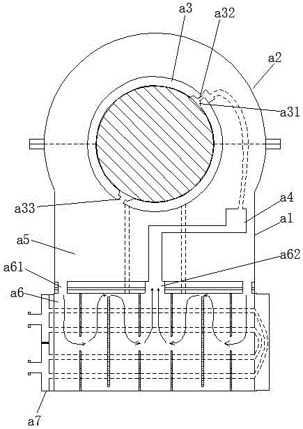
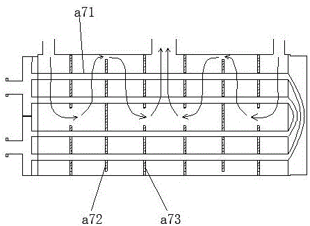
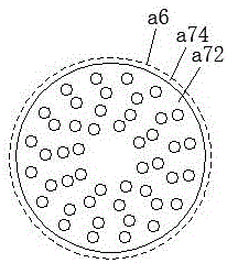
[0117] An oil channel balanced bearing, such as Figure 5 , Figure 6 and Figure 7 As shown, it includes bearing seat 1, bearing cover 2, shoe seat 3, support shoe 41, forward thrust shoe 42, reverse thrust shoe 43, forward thrust plate 51, reverse thrust plate 52, first oil chamber 6, second oil chamber 7. Cooler 8 and oil cover 9; the bearing cover 2 is used to cover the top of the bearing seat 1, the shoe seat 3 is fixed on the bearing seat 1, and the supporting shoe 41 is fixed on the inner diameter of the shoe seat 3 side, the axial ends of the tile seat 3 are the front end and the rear end respectively, the forward thrust shoe 42 is fixed on the front end of the tile seat 3, the reverse thrust shoe 43 is fixed on the rear end of the tile seat 3, and the forward thrust The disk 51 is attached to the front end of the forward thrust pad 42, the reverse thrust pad 43 is attached to the rear end of the reverse thrust pad 43, and the forward thrust disk 51 and the reverse t...

Embodiment 2

[0130] The difference from Embodiment 1 is that: Figure 19 As shown, the inner surface of the support shoe 41 includes at least two oil injection grooves 411 , and the oil injection grooves 411 are spirally distributed on the inner surface of the support shoe 41 . With the conventional oil tank structure, the oil film fracture is prone to occur in the area far away from the oil tank. The sliding friction of the oil film fracture zone produces large heat, the heat conduction speed is slow, and it is easy to cause the burning of the pads; this method can effectively prevent the fracture of the oil film between the bearing pad and the shaft body.

[0131] Using the implementation of the above example, it is used to test the support shoe 41 and the oil temperature of the bearing. After three hours of operation, the temperature of the support shoe 41 tends to be stable within 44.5°C, and the oil temperature tends to be stable at about 35°C.

Embodiment 3

[0133] The difference from Embodiment 1 is that: Figure 20 As shown, the oil discharge groove 412 includes a first oil discharge groove 412a and a second oil discharge groove 412b, the first oil discharge groove 412a and the second oil discharge groove 412b are respectively located at the two ends of the oil injection groove 411, and the first oil discharge groove 412a is connected to the oil injection groove 412b. The distance between the oil grooves 411 is 30mm, the distance between the second oil discharge groove 412b and the oil injection groove 411 is 30mm, and the first oil discharge groove 412a is provided with an oil discharge hole 414, and the first oil discharge groove 412a passes through the oil discharge hole 414 and The first oil chamber 6 communicates, and the second oil discharge groove 412 b is a semi-open groove, directly communicating with the first oil chamber 6 .

[0134] Using the implementation of the above example, it is used to test the support shoe 41...


PUM


Abstract

The invention discloses an oil duct balance type bearing. The oil duct balance type bearing comprises a bearing base, a tilting fillet, a positive thrust disc, a first oil cavity, a second oil cavity, a cooler and a cover with oil, wherein the tilting fillet is fixedly arranged on the bearing base; a supporting pad is arranged at the inner radial side of the tilting fillet; a positive thrust pad is arranged at the front side of the tilting fillet; the second oil cavity communicates with the first oil cavity through a hot oil inlet; the cooler is mounted in the second oil cavity; the cover with oil and the positive thrust disc form a cavity with oil; an oil injecting slot is formed in the inner radial side of the supporting pad; an oil throwing cavity is arranged at the inner radial side of the positive thrust pad; the cavity with oil comprises a high-pressure oil outlet and an oil pumping hole; the oil pumping hole communicates with the second oil cavity; the high-pressure oil outlet separately communicates with the oil injecting slot and the oil throwing cavity through a first oil duct and a second oil duct; and a first flow regulating valve and a second flow regulating valve are separately arranged in the first oil duct and the second oil duct. The oil duct balance type bearing has relatively high heat exchange efficiency, and can prevent a bearing bush from being burnt.

Description

technical field [0001] The invention relates to the field of bearing devices, in particular to generator or motor bearings. Background technique [0002] Bearings are an important part of contemporary mechanical equipment. Its main function is to support the mechanical rotating body, reduce the friction coefficient during its movement, and ensure its rotation accuracy. According to the different friction properties of moving elements, bearings can be divided into two categories: rolling bearings and sliding bearings. [0003] Rolling bearings are generally composed of four parts: inner ring, outer ring, rolling body and cage. The function of the inner ring is to cooperate with the shaft and rotate together with the shaft; the function of the outer ring is to cooperate with the bearing seat to play a supporting role; The cage evenly distributes the rolling elements between the inner ring and the outer ring, and its shape, size and quantity directly affect the performance an...

Claims


Application Information

Patent Timeline
IPC IPC(8): F16C17/10F16C37/00
CPCF16C17/10F16C37/00F16C2360/00
Inventor 郭远军
Owner 郭远军
Why Eureka
Try Eureka