Slewing device for transmission, transmission equipment including same and transmission method
A technology for slewing devices and transmission equipment, applied in the direction of transmission devices, friction transmission devices, transmission device parts, etc., can solve the problems of poor impact resistance and rigidity, low transmission efficiency, and poor operation stability of the whole machine, so as to improve the carrying capacity , reduce the purchase cost, reduce the effect of moving resistance
- Summary
- Abstract
- Description
- Claims
- Application Information
AI Technical Summary
Problems solved by technology
Method used
Image

Examples
Embodiment 1
[0051] This embodiment provides a slewing device 1 that can be used as a main part of an intermediate transmission in a multi-stage transmission.
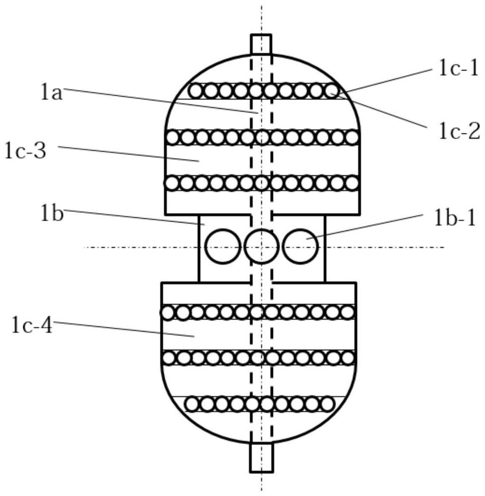
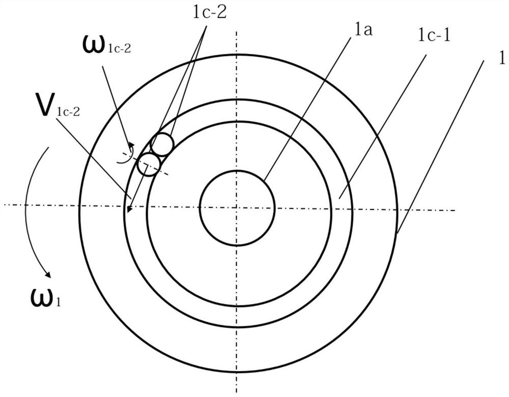
[0052] like figure 2 As shown, the swivel device 1 includes a base body 1c. End-to-end raceways 1c-1 are arranged on the base body 1c. The raceway 1c-1 is used to accommodate several first rollers 1c-2. Preferably, the first rolling element 1c-2 is a rolling part formed by rotation, which can revolve around the axis of the base body 1c on the raceway 1c-1 in a manner of self-rotation on its own axis. For example, the first roller 1c-2 may be a sphere, an ellipsoid, a cylinder or a cone. Adjacent two first rollers 1c-2 are in partial contact with each other. The first roller 1c-2 is also in partial contact with the raceway 1c-1. In the case where two adjacent first rollers 1c-2 are in partial contact with each other, several rollers 1c-2 fill the raceway 1c-1 in such a way that the raceways 1c-1 are in partial contact with eac...
Embodiment 2
[0059] This embodiment may be a further improvement and / or supplement to Embodiment 1, and repeated content will not be repeated here. In the case of no conflict or contradiction, the whole and / or part of the content of the preferred implementations of other embodiments may serve as supplements to this embodiment.
[0060] Preferably, the axis of the rotary device 1 and the axis of the first transmission turntable 1b can be set in such a way that they do not coincide with each other but are in the same direction. Due to the eccentric setting of the first transmission turntable 1b, when the slewing device 1 rotates around its own axis, the first transmission turntable 1b rotates eccentrically around the axis of the slewing device 1, so that the rolling hole 1b-1 on the first transmission turntable 1b The dynamic friction pair is formed in discontinuous contact with the second roller 3 b - 3 on the first transmission member 3 , so that the first transmission member 3 rotates int...
Embodiment 3
[0062] This embodiment may be a further improvement and / or supplement to Embodiment 1, and repeated content will not be repeated here. In the case of no conflict or contradiction, the whole and / or part of the content of the preferred implementations of other embodiments may serve as supplements to this embodiment. This embodiment discloses a transmission device.
[0063] Preferably, the transmission device includes a slewing device 1 and a second transmission member 2 to realize one-stage transmission.
[0064] Or, preferably, the transmission device includes a slewing device 1 and a first transmission member 3 to realize a first-stage transmission.
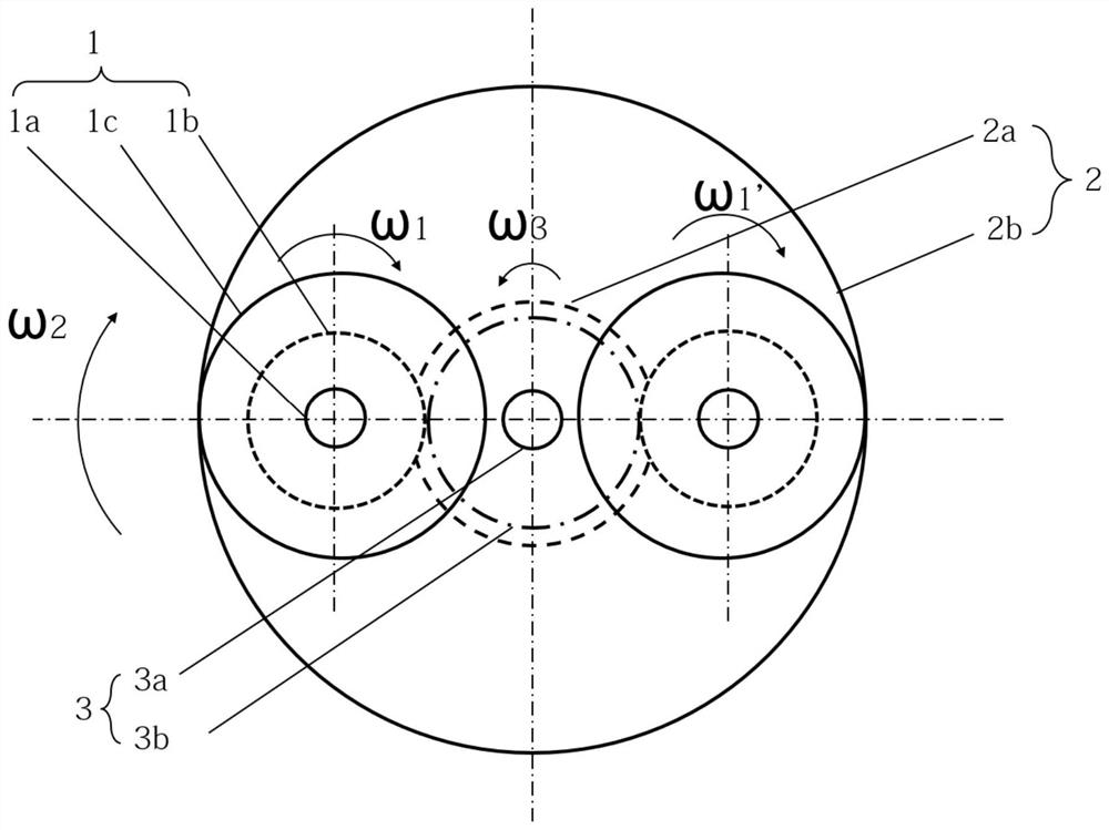
[0065] Or, preferably, the transmission device includes a slewing device 1 , a first transmission member 3 and a second transmission member 2 to realize two-stage transmission. Its specific operation diagram is as follows figure 1 shown. The external power drives the second transmission part 2 as the active part with ω 2 Rot...
PUM
 Abstract
Description
Claims
Application Information
 - R&D
- Intellectual Property
- Life Sciences
- Materials
- Tech Scout
- Unparalleled Data Quality
- Higher Quality Content
- 60% Fewer Hallucinations
Browse by: Latest US Patents, China's latest patents, Technical Efficacy Thesaurus, Application Domain, Technology Topic, Popular Technical Reports.
© 2025 PatSnap. All rights reserved.Legal|Privacy policy|Modern Slavery Act Transparency Statement|Sitemap|About US| Contact US: help@patsnap.com