A self-lubricating micro-stir friction welding method with welding friction restraint

A micro-stirring and friction welding technology, applied in welding equipment, non-electric welding equipment, metal processing equipment, etc., can solve problems such as deformation, welding failure, and difficulty in welding workpiece assembly, reduce post-weld deformation, increase heat input, Realize the effect of high-speed welding

Active Publication Date: 2021-11-16
SHANGHAI AEROSPACE EQUIP MFG GENERAL FACTORY
View PDF9 Cites 0 Cited by
  • Summary
  • Abstract
  • Description
  • Claims
  • Application Information

AI Technical Summary

Problems solved by technology

[0007] In order to solve the above-mentioned practical engineering problems and the shortcomings of existing methods, the present invention proposes a micro-stir friction welding method using self-lubricating welding friction restraint, which can maintain the flatness of the workpiece before welding and reduce the welding seam to a certain extent. Residual stress solves problems such as difficulty in assembling welding workpieces during friction stir welding of thin-walled components, welding failure due to deformation during welding, and effectively realizes high-reliability and high-efficiency welding of thin-walled components

Method used


Image

  • A self-lubricating micro-stir friction welding method with welding friction restraint
  • A self-lubricating micro-stir friction welding method with welding friction restraint

Examples


specific Embodiment approach 1

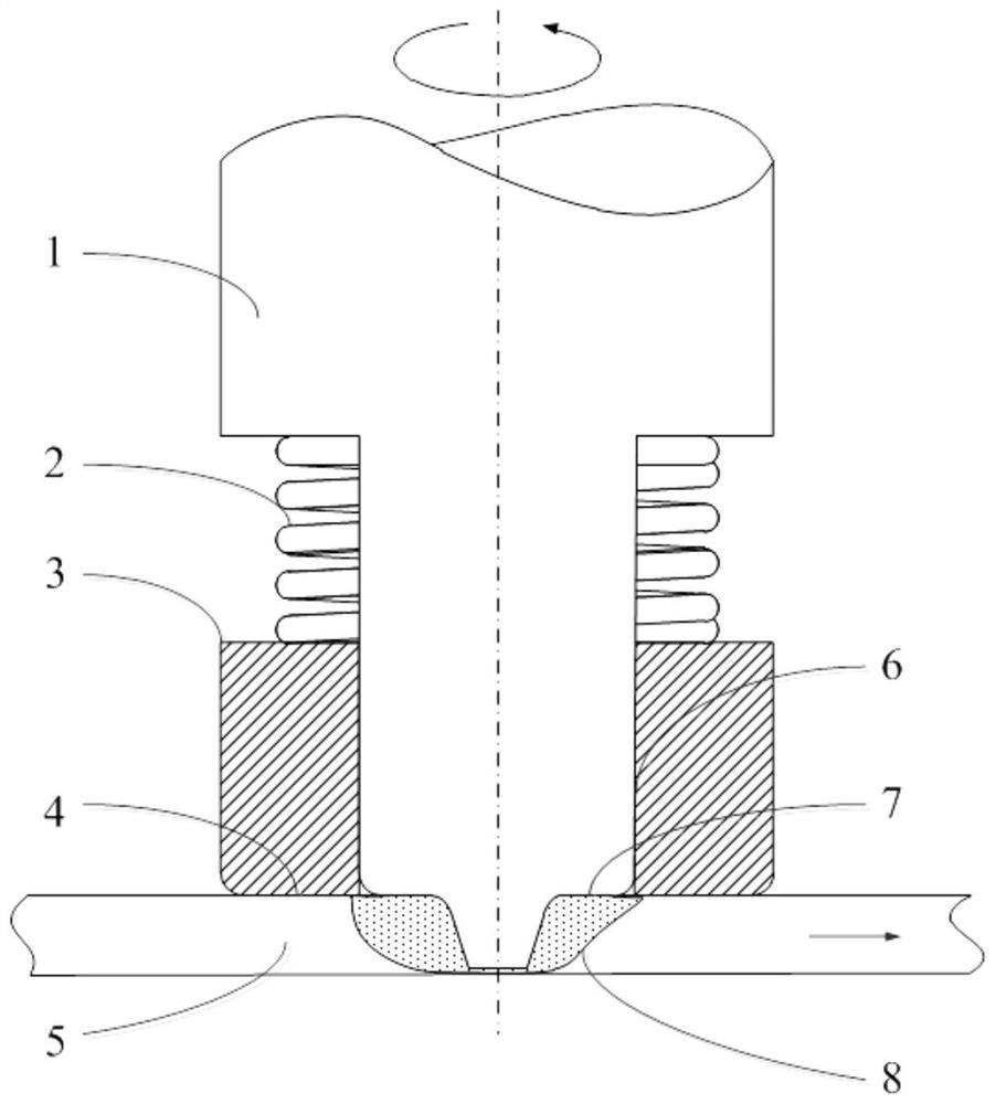
[0019] Specific implementation mode one: combine figure 1 Describe this embodiment, this embodiment includes traditional micro-friction stir welding stirring head 1, welding thickness 0.5mm, stirring needle length 0.45mm, stirring head shaft shoulder diameter 3.6mm, auxiliary shaft shoulder 3 outer diameter 20mm, auxiliary shaft shoulder 3 The connection surface 6 with the stirring head 1 adopts two symmetrical limiting rib grooves for torque transmission; the spring 2 has 4 turns, an outer diameter of 18mm, and provides a pressing force of 3kg under normal welding compression. On the upper part of the stirring head 1, it is connected with the welding machine tool through a quick chuck. The welding speed is 10000rpm, the welding speed is 1.5m / min, and the pressing amount is 0.03mm. The auxiliary shoulder 3 is made of PEEK composite material, and the outer edge of the contact end surface 4 is chamfered with R2 to form a shape convex from the outside to the inside. The contact ...

specific Embodiment approach 2

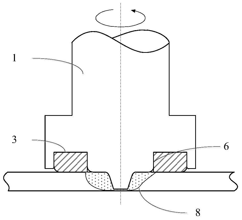
[0020] Specific implementation mode two: combination figure 2 Describe this embodiment. This embodiment includes a traditional micro-friction stir welding stirring head 1 with a welding thickness of 1 mm. On the outside of the shoulder of the stirring head 1, an annular cavity is added, and the cavity is embedded with a self-lubricating material as an auxiliary shoulder. 3. The connecting end face 6 of the auxiliary shaft shoulder 3 and the stirring head 1 adopts a tight fit and two symmetrical limit rib grooves for connection and torque transmission. The diameter of the shaft shoulder of the stirring head is 6mm, the diameter of the stirring needle is 2.5mm, and the length of the stirring needle is 0.9mm mm, the outer diameter of the auxiliary shoulder is 30mm, the welding speed is 8000rpm, the welding force is 0.06mm, and the welding speed is 1m / min. The pressing force of the auxiliary shoulder in this embodiment is controlled by the amount of pressing down of the stirring ...


PUM

PropertyMeasurementUnit
thermal resistanceaaaaaaaaaa

Abstract

A self-lubricating micro-stir friction welding method with welding friction restraint of the present invention, a low friction coefficient auxiliary shoulder that rotates with the stirring head is added to the outside of the friction stir welding stirring head of the thin-walled member, and the shoulder is adopted with a certain high temperature resistance A self-lubricating material with high capacity, which can partially restrain the material to be welded and roll it after welding, so as to keep the workpiece flat before and after welding. At the same time, the auxiliary shoulder can adjust and control the pressure or displacement of the workpiece. The auxiliary shoulder and the stirring head rotate together, and the welding method with almost no inclination angle can overcome the problem of excessive resistance of the static shoulder. The material has a very small friction coefficient, and its heat production is low, which will not significantly increase the heat input of the welding process, which can ensure the dynamic restraint effect on thin-walled workpieces without affecting the welding process. The invention can effectively solve the problems of difficult assembly, easy deformation and instability, large deformation after welding and the like in the friction stir welding process of thin-walled components.

Description

technical field [0001] The invention relates to a micro-stir friction welding method for self-lubricating welding friction restraint, which belongs to the field of welding. Background technique [0002] In aerospace, consumer electronics and other fields, there is a wide demand for welding light materials such as aluminum alloys and magnesium alloys with a wall thickness of 1mm or less. However, due to the thin wall thickness of such components, the traditional arc welding technology has a large heat input, which usually leads to material instability and deformation, and is difficult to weld such components. Laser and other high-energy beam welding technologies usually have a high incidence of forming defects due to the high reflectivity of aluminum alloys to laser light and the instability of the molten pool, which also limits the application of this joining technology. [0003] Friction stir welding technology is a solid-phase joining technology, which has the advantages ...

Claims


Application Information

Patent Timeline
Patent Type & Authority Patents(China)
IPC IPC(8): B23K20/12B23K20/26
CPCB23K20/1245
Inventor 封小松夏佩云董吉义赵慧慧
Owner SHANGHAI AEROSPACE EQUIP MFG GENERAL FACTORY
Why Eureka
Try Eureka