Water Vapor Distillation Apparatus, Method and System

a technology of water vapor distillation and water vapor, applied in the field of water distillation, can solve the problems of large-scale water systems that require both significant infrastructure and highly trained operators, and the techniques are only well suited to centralized water systems

Active Publication Date: 2014-07-03
DEKA PROD LLP
View PDF4 Cites 28 Cited by
  • Summary
  • Abstract
  • Description
  • Claims
  • Application Information

AI Technical Summary

Benefits of technology

[0019]Some embodiments of this aspect of the present invention include one or more of the following: wherein the apparatus further includes at least one controller, an idle state wherein the at least one controllers are off, a fill state wherein the source valve is opened and source fluid enters a sump in the fluid vapor distillation apparatus, a heat state wherein a heater in the sump is maximized until fluid in the sump reaches a predetermined temperature, a heat exchanger prime state wherein the source valve is opened to a predetermined duty cycle, a start pump state wherein a bearing feed pump is run at a predetermined speed, and a blow motor is started, and a run state wherein the fluid vapor distillation apparatus produces product water. Wherein the apparatus further includes including a source fluid input, an evaporator condenser apparatus including a substantially cylindrical housing, and a plurality of tubes in the housing, whereby the source fluid input is fluidly connected to the evaporator condenser and the evaporator condenser transforms source fluid into steam and transforms compressed steam into product fluid, a heat exchanger fluidly connected to the source fluid input and a product fluid output, the heat exchanger including an outer tube, and at least one inner tube, and a regenerative blower fluidly connected to the evaporator condenser, whereby the regenerative blower compresses steam, and whereby compressed steam flows to the evaporative condenser whereby compressed steam is transformed into product fluid. Wherein the heat exchanger is disposed about the housing of the evaporator condenser. Wherein the heat exchanger further includes wherein the outer tube is a source fluid flow path and the at least one inner tube is a product fluid flow path. Wherein the heat exchanger further includes at least three inner tubes. Wherein the at least three inner tubes are twined to form a substantially helical shape. Wherein the heat exchanger further includes two ends, and at each end a connector is attached, whereby the connectors form a connection to the evaporator condenser. Wherein the evaporator condenser tubes further includes packing inside the tubes. Wherein the packing is a rod. Wherein the evaporator condenser further including a steam chest fluidly connected to the plurality of tubes. Wherein the regenerative blower further includes an impeller assembly driven by a magnetic drive coupling. Wherein the control system includes at least two processors, a motor control engine processor and an ARM processor. Wherein the fluid vapor distillation apparatus further includes a conductivity meter and a conductivity cell to determine the conductivity of the product fluid.
[0020]In accordance with another aspect of the present invention, a water vapor distillation apparatus is disclosed. The apparatus includes a control system for controlling the water vapor distillation apparatus, the control system including at least one controller, an idle state wherein the at least one controllers are off, a fill state wherein the source valve is opened and source fluid enters a sump in the fluid vapor distillation apparatus, a heat state wherein a heater in the sump is maximized until fluid in the sump reaches a predetermined temperature, a heat exchanger prime state wherein the source valve is opened to a predetermined duty cycle, a start pump state wherein a bearing feed pump is run at a predetermined speed, and a blow motor is started, and a run state wherein the fluid vapor distillation apparatus produces product water.
[0021]Some embodiments of this aspect of the present invention include one or more of the following: Wherein the control system further includes a blow down controller for controlling a blow down valve, a source flow controller for controlling a source flow valve, and a blow down level sensor in communication with a blow down controller and a source flow controller, the blow down level sensor sends signals related to the blow down level to the blow down controller and the source flow controller indicative of the blow down level, wherein the source flow controller actuates the source flow valve based at least on the blow down level sensor signals, and wherein the blow down controller actuates the blow down valve based at least on the blow down level sensor signals, whereby the blow down level and the source flow level are maintained using the blow down level sensor signals as input. Wherein the apparatus further includes a source fluid input, an evaporator condenser apparatus including a substantially cylindrical housing, and a plurality of tubes in the housing, whereby the source fluid input is fluidly connected to the evaporator condenser and the evaporator condenser transforms source fluid into steam and transforms compressed steam into product fluid, a heat exchanger fluidly connected to the source fluid input and a product fluid output, the heat exchanger including an outer tube, and at least one inner tube, and a regenerative blower fluidly connected to the evaporator condenser, whereby the regenerative blower compresses steam, and whereby compressed steam flows to the evaporative condenser whereby compressed steam is transformed into product fluid. Wherein the heat exchanger is disposed about the housing of the evaporator condenser. Wherein the heat exchanger further includes wherein the outer tube is a source fluid flow path and the at least one inner tube is a product fluid flow path. Wherein the heat exchanger further includes at least three inner tubes. Wherein the at least three inner tubes are twined to form a substantially helical shape. Wherein the heat exchanger further includes two ends, and at each end a connector is attached, whereby the connectors form a connection to the evaporator condenser. Wherein the evaporator condenser tubes further includes packing inside the tubes. Wherein the packing is a rod. Wherein the evaporator condenser further including a steam chest fluidly connected to the plurality of tubes. Wherein the regenerative blower further includes an impeller assembly driven by a magnetic drive coupling. Wherein the control system includes at least two processors, a motor control engine processor and an ARM processor. Wherein the fluid vapor distillation apparatus further includes a conductivity meter and a conductivity cell to determine the conductivity of the product fluid.
[0022]In accordance with one aspect of the present invention, a fluid vapor distillation apparatus is disclosed. The apparatus includes a source fluid input, and an evaporator condenser apparatus. The evaporator condenser apparatus includes a substantially cylindrical housing and a plurality of tubes in the housing. The source fluid input is fluidly connected to the evaporator condenser and the evaporator condenser transforms source fluid into steam and transforms compressed steam into product fluid. Also included in the fluid vapor distillation apparatus is a heat exchanger fluidly connected to the source fluid input and a product fluid output. The heat exchanger includes an outer tube and at least one inner tube. Also included in the fluid vapor distillation apparatus is a regenerative blower fluidly connected to the evaporator condenser. The regenerative blower compresses steam, and the compressed steam flows to the evaporative condenser where compressed steam is transformed into product fluid. The fluid vapor distillation apparatus also includes a control system.
[0023]Some embodiments of this aspect of the present invention include one or more of the following: where the heat exchanger is disposed about the housing of the evaporator condenser; where the heat exchanger further includes wherein the outer tube is a source fluid flow path and the at least one inner tube is a product fluid flow path; where the heat exchanger further includes at least three inner tubes; where the at least three inner tubes are twined to form a substantially helical shape; where the heat exchanger further includes two ends, and at each end a connector is attached, whereby the connectors form a connection to the evaporator condenser; where the evaporator condenser tubes further include packing inside the tubes; where the packing is a rod; where the evaporator condenser further includes a steam chest fluidly connected to the plurality of tubes; and where the regenerative blower further comprising an impeller assembly driven by a magnetic drive coupling.

Problems solved by technology

Many of these techniques are significantly affected by variations in the water quality and do not address a wide variety of common contaminants, such as bacteria, viruses, organics, arsenic, lead, mercury, and pesticides that may be found in water supplies in the developing world and elsewhere.
Moreover, some of these techniques are only well suited to centralized, large-scale water systems that require both a significant infrastructure and highly trained operators.
However, the poor financial resources, limited technical assets, and low population density that does not make it feasible to build centralized, large-scale water systems in much of the developing world, also limits the availability of adequate, affordable, and reliable power to operate vapor compression distillation systems, as well as hindering the ability to properly maintain such systems.

Method used


Image

  • Water Vapor Distillation Apparatus, Method and System
  • Water Vapor Distillation Apparatus, Method and System
  • Water Vapor Distillation Apparatus, Method and System

Examples


Embodiment Construction

[0380]Definitions. As used in this description and the accompanying claims, the following terms shall have the meanings indicated, unless the context otherwise requires.

[0381]The term “fluid” is used herein to include any type of fluid including water. Thus, although the exemplary embodiment and various other embodiments are described herein with reference to water, the scope of the apparatus, system and methods includes any type of fluid. Also, herein, the term “liquid” may be used to indicate the exemplary embodiment, where the fluid is a liquid.

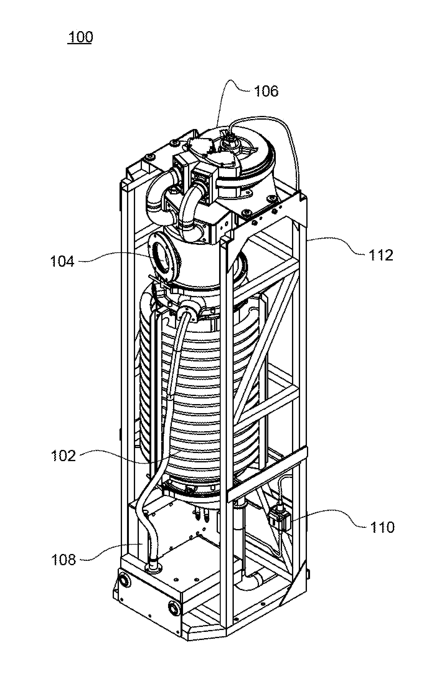
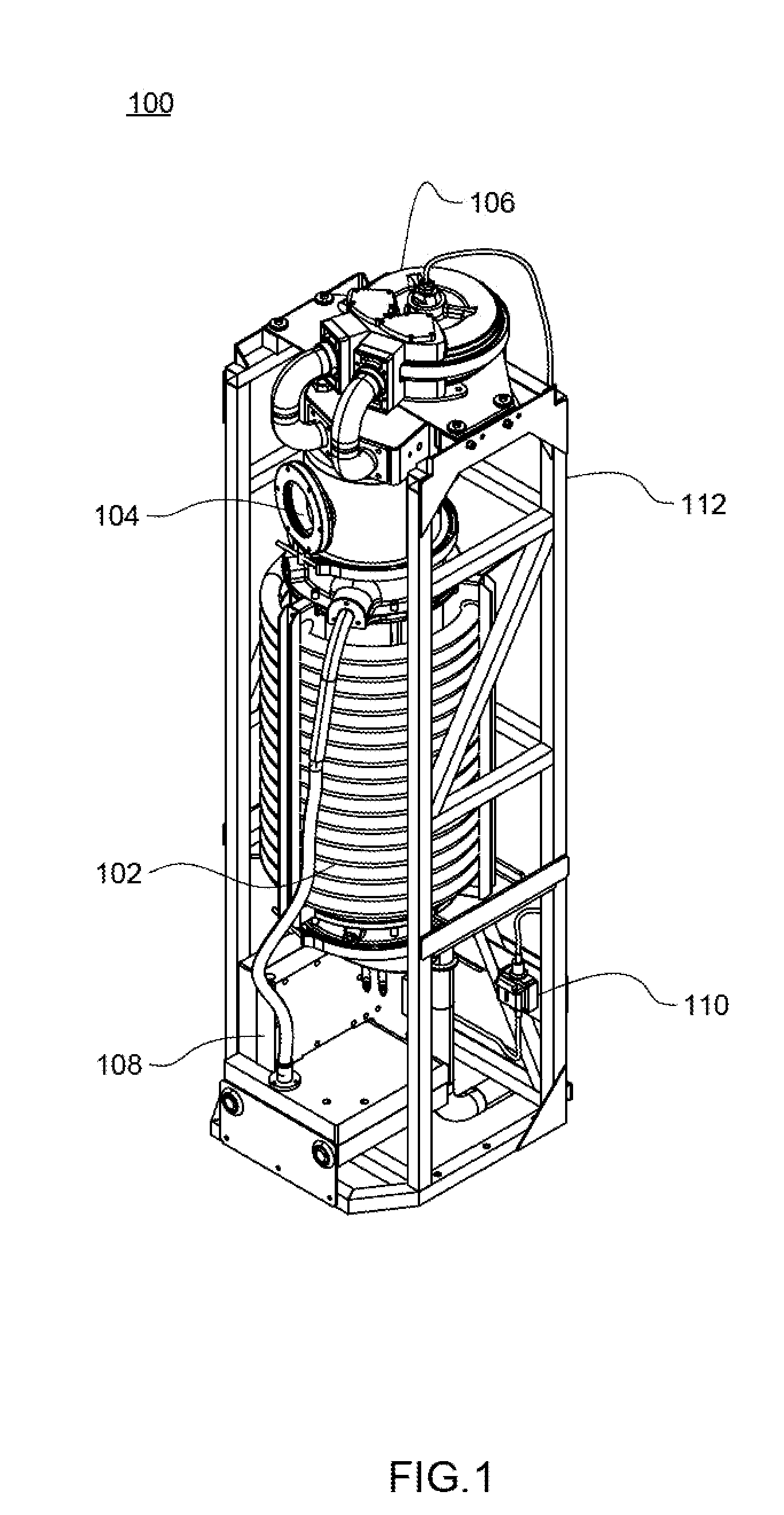
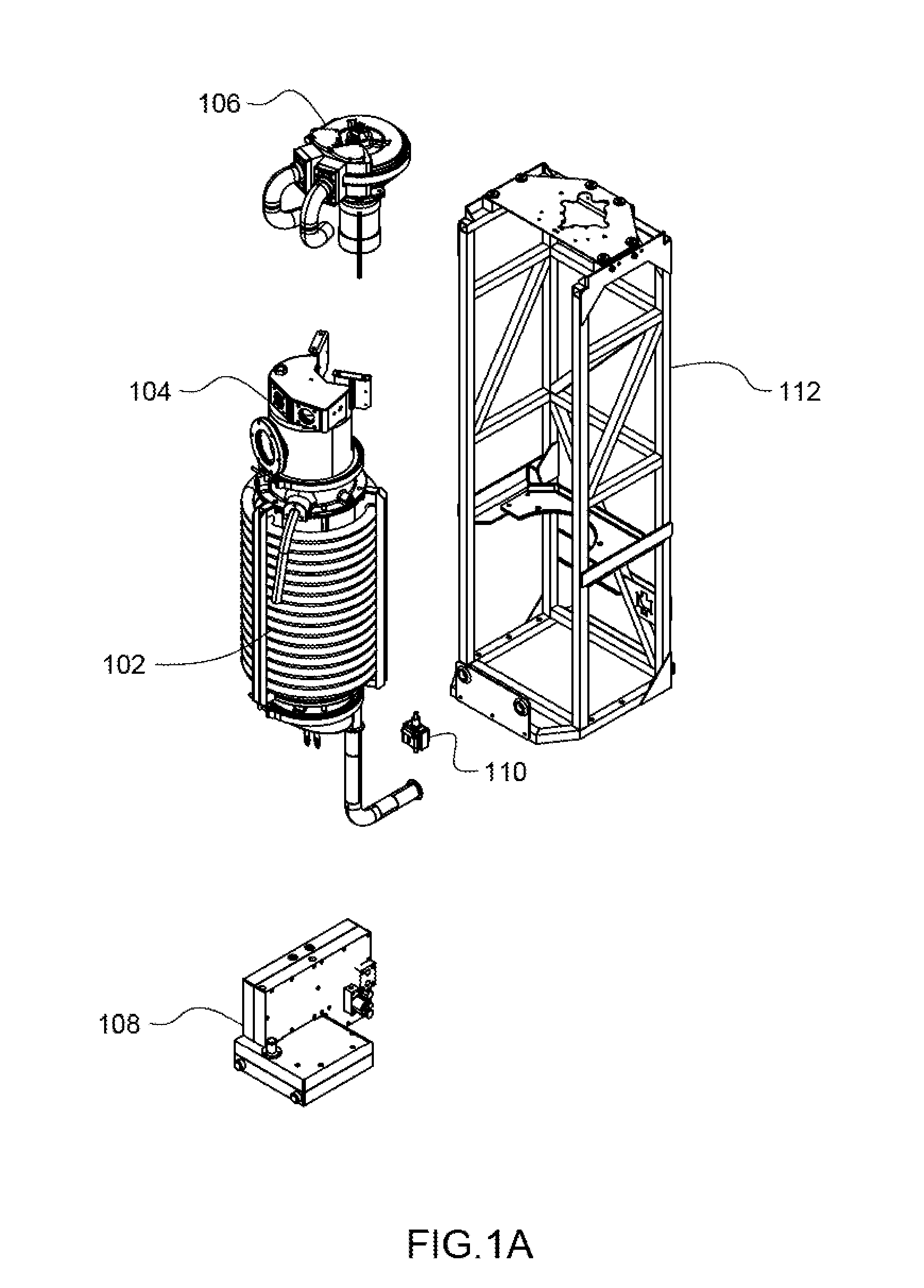
[0382]The term “evaporator condenser” is used herein to refer to an apparatus that is a combination evaporator and condenser. Thus, a structure is referred to as an evaporator condenser where the structure itself serves as both. The evaporator condenser structure is referred to herein as an evaporator / condenser, evaporator condenser or evaporator and condenser. Further, in some instances, where either the evaporator or the condenser is bei...


PUM

PropertyMeasurementUnit
diameteraaaaaaaaaa
diameteraaaaaaaaaa
lengthaaaaaaaaaa

Abstract

A fluid vapor distillation system. The system includes a control system for controlling a fluid vapor distillation apparatus including a blow down controller for controlling a blow down valve, a source flow controller for controlling a source flow valve, and a blow down level sensor in communication with a blow down controller and a source flow controller, the blow down level sensor sends signals related to the blow down level to the blow down controller and the source flow controller indicative of the blow down level, wherein the source flow controller actuates the source flow valve based at least on the blow down level sensor signals, and wherein the blow down controller actuates the blow down valve based at least on the blow down level sensor signals, whereby the blow down level and the source flow level are maintained using the blow down level sensor signals as input.

Description

CROSS REFERENCE TO RELATED APPLICATIONS[0001]The present application is a Continuation-in-Part Application of U.S. patent application Ser. No. 13 / 982,022, filed Jul. 26, 2013 and entitled Water Vapor Distillation Apparatus, Method and System (Attorney Docket No. K95), which is a U.S. National Stage Application under 35 USC 371 of PCT Application Serial No. PCT / US12 / 46740, filed Jul. 13, 2012 and entitled Water Vapor Distillation Apparatus, Method and System (Attorney Docket No. I83WO), which claims priority to U.S. patent application Ser. No. 13 / 184,169, filed Jul. 15, 2011 and entitled Water Vapor Distillation Apparatus, Method and System (Attorney Docket No. 183), each of which is hereby incorporated herein by reference in their entireties.[0002]The present application also claims priority from U.S. Provisional Patent Application Ser. No. 61 / 819,919, filed May 6, 2013 and entitled Water Vapor Distillation Apparatus, Method and System (Attorney Docket No. K58), and U.S. Provisional...

Claims


Application Information

Patent Timeline
Patent Type & Authority Applications(United States)
IPC IPC(8): C02F1/04
CPCC02F1/041B01D1/0058B01D1/2896B01D3/007B01D3/42C02F1/008C02F1/048C02F1/16C02F2209/05Y02W10/37
Inventor KAMEN, DEANLAROCQUE, RYAN K.LANGENFELD, CHRISTOPHER C.SCHNELLINGER, ANDREW A.BHAT, PRASHANTCLAPP, OTIS L.SMITH, STANLEY B.ENT, STEPHEN M.
Owner DEKA PROD LLP
Why Eureka
Try Eureka