Method and Apparatus for High-Voltage DC Charging of Battery-Electric and Plug-in Hybrid Electric Vehicles

a hybrid electric vehicle and high-voltage charging technology, applied in the direction of electric devices, battery/fuel cell control arrangements, transportation and packaging, etc., can solve the problems of adversely affecting travel plans, not as ubiquitous or conveniently located charging stations for electrified vehicles, etc., and achieve the effect of convenient transportation

Active Publication Date: 2014-07-03
FORD GLOBAL TECH LLC
View PDF5 Cites 20 Cited by
  • Summary
  • Abstract
  • Description
  • Claims
  • Application Information

AI Technical Summary

Benefits of technology

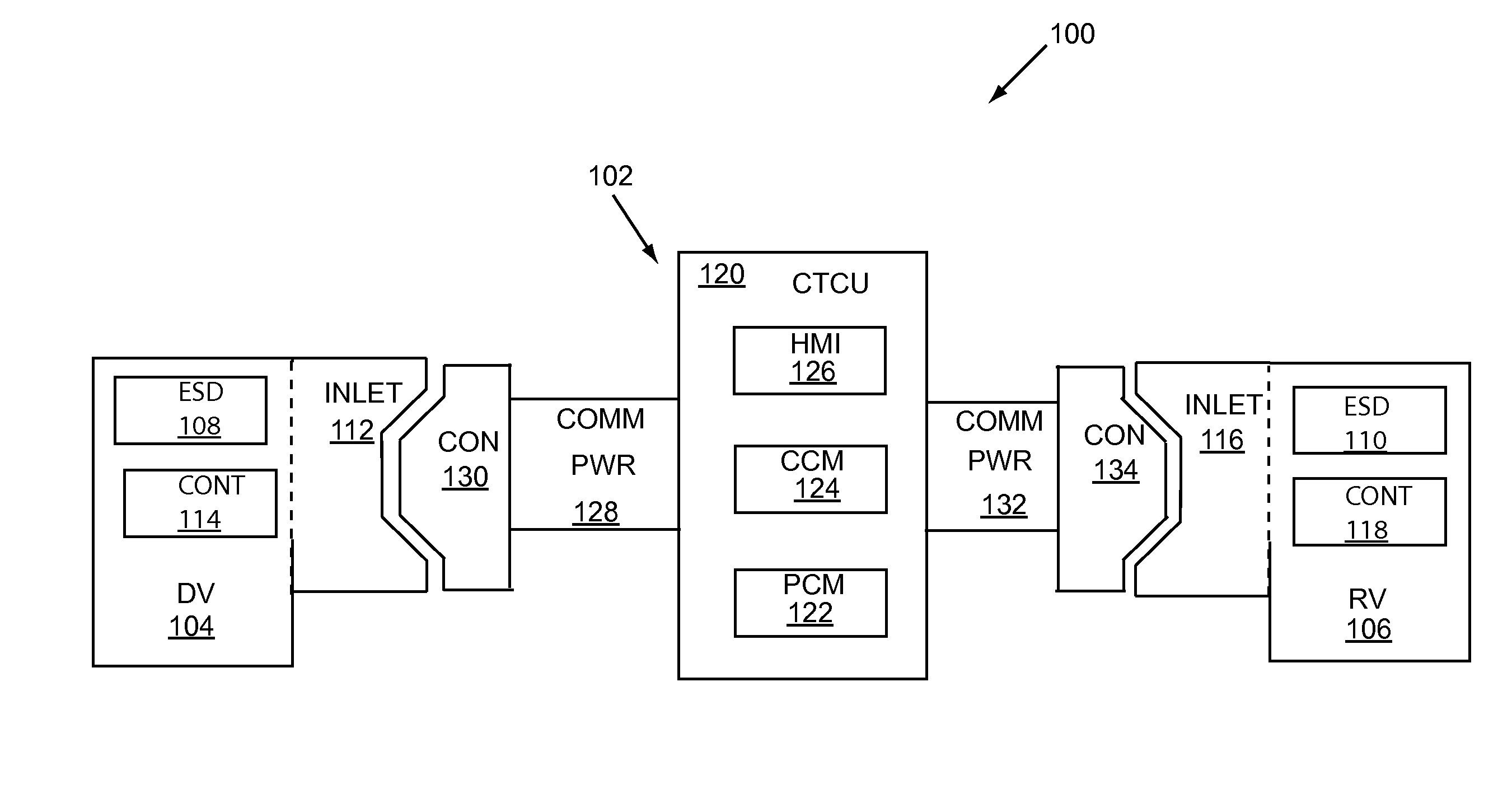
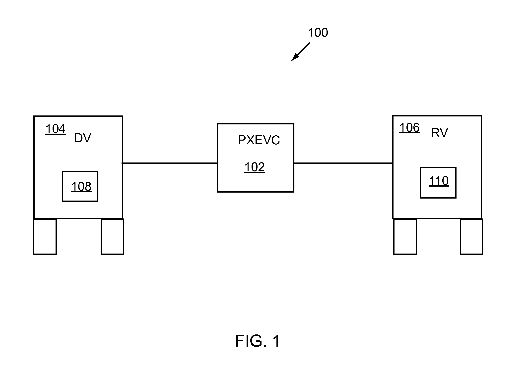
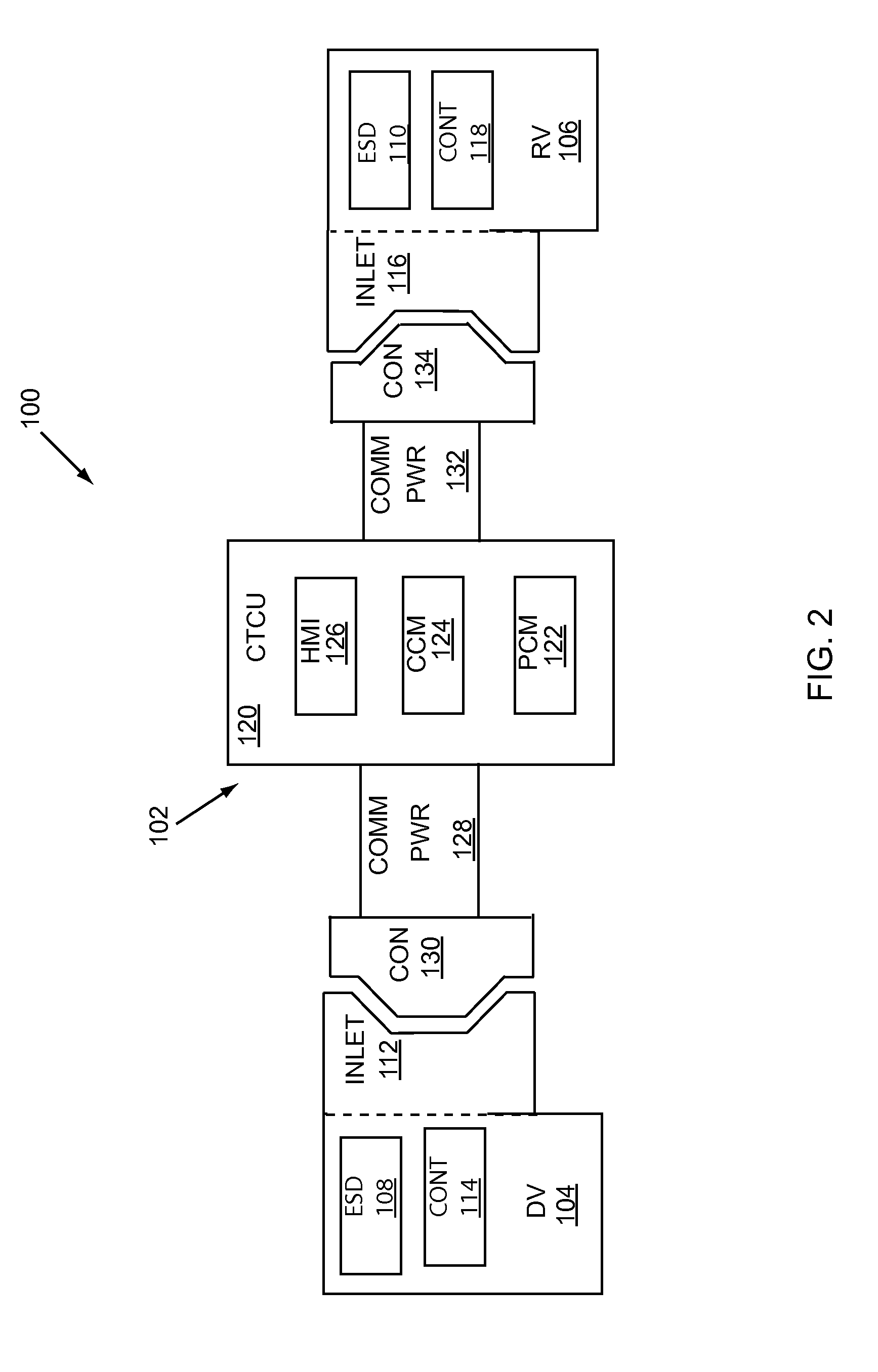
[0009]A charging apparatus can include a first connector configured for coupling to a recipient vehicle, a second connector configured for coupling to a donor vehicle, and a controller unit for controllably transferring energy between said donor and recipient vehicles. An example charging apparatus can be configured to enable direct current (DC) charging of the recipient vehicle battery by the donor vehicle battery. In an example embodiment, a charging apparatus is embodied as a portable device that can be easily transported, for example it can be stowed at a donor or recipient vehicle. An exemplary charging apparatus can comprise a power conversion module configured to transfer energy between the donor and receiver batteries, and a processor module configured for communication with the donor and recipient vehicles and for controlling energy transfer by the power conversion module. In an example embodiment, a charging apparatus can perform voltage matching between the donor and receiver batteries.

Problems solved by technology

One potential problem with such a scenario, however, is that charging stations for electrified vehicles are generally not as ubiquitous or conveniently located as conventional gasoline stations.
While long charging times can be acceptable when charge transfer is performed at predetermined times and locations, an extended recharging period can adversely affect travel plans when the process must be conducted unexpectedly.

Method used


Image

  • Method and Apparatus for High-Voltage DC Charging of Battery-Electric and Plug-in Hybrid Electric Vehicles
  • Method and Apparatus for High-Voltage DC Charging of Battery-Electric and Plug-in Hybrid Electric Vehicles
  • Method and Apparatus for High-Voltage DC Charging of Battery-Electric and Plug-in Hybrid Electric Vehicles

Examples


Embodiment Construction

[0017]As required, example embodiments of the present invention are disclosed. The various embodiments are meant to be non-limiting examples of various ways of implementing the invention and it is understood that the invention may be embodied in alternative forms. The present invention will be described more fully hereinafter with reference to the accompanying drawings in which like numerals represent like elements throughout the several figures, and in which example embodiments are shown. The figures are not necessarily to scale and some features may be exaggerated or minimized to show details of particular elements, while related elements may have been eliminated to prevent obscuring novel aspects. The specific structural and functional details disclosed herein should not be interpreted as limiting, but merely as a basis for the claims and as a representative basis for teaching one skilled in the art to variously employ the present invention. For example, while the exemplary embod...


PUM


Abstract

A portable charging device can provide controllable fast DC charging of an electric vehicle (EV) high voltage battery by a separate EV high voltage battery. The charging device can be configured to comply with universal standards for EV charging so as to be compatible with various automobile models of various manufacturers. The device can be configured to establish a communication link with a donor and recipient vehicle and conduct a voltage matching process between the batteries of the two vehicles prior to transferring power to the recipient vehicle battery. To prevent energy theft, control of a charging process can be shared among the charging device and the donor and receiver vehicles. A charger device can be configured to enable a charging process only when no faults are detected. A charger device can allow a motorist to quickly recharge a depleted high voltage battery at a convenient time and location.

Description

BACKGROUND OF INVENTION[0001]1. Field of Art[0002]This invention relates generally to charging of electrified vehicles, and more particularly to portable DC charging devices.[0003]2. Background Art[0004]In conventional and hybrid electric automobiles, an internal combustion engine can provide motoring power, and a low voltage battery can provide power for devices such as a starter motor, a cabin ventilation system, internal and external lights, an entertainment system and the like. In general, with a gasoline-powered engine a vehicle with full fuel reservoir can drive around 300 or more miles. When the fuel supply for the engine is depleted, it can be replenished with a brief stop at a service station. In desperate circumstances, when a vehicle is stranded without fuel in a remote area, a simple hose can be used to siphon gasoline from the fuel tank of an accommodating passing motorist who stops to assist. Similarly, when the charge of a conventional low voltage automobile battery d...

Claims


Application Information

Patent Timeline
Patent Type & Authority Applications(United States)
IPC IPC(8): B60L11/18
CPCB60L11/1818Y02T90/16Y02T90/14B60L3/00B60L3/0069B60L2210/10B60L2270/32Y04S30/14B60L53/16B60L53/65B60L53/18H02J1/122H02J7/342B60L58/22H02J2310/48Y02T10/72Y02T10/7072Y02T10/70Y02T90/12Y02T90/167Y02T10/92
Inventor LOFTUS, MICHAEL EDWARDPROIETTY, JOHNSYED, FAZAL URRAHMANTABATOWSKI-BUSH, BEN A.MACNEILLE, PERRY ROBINSON
Owner FORD GLOBAL TECH LLC
Why Eureka
Try Eureka