
Device and Method for Erythrocyte Morphology Analysis

a morphological analysis and erythrocyte technology, applied in the field of devices and methods for performing morphological analysis of erythrocytes in samples, can solve the problems of patient diagnosis delay, high workload for workers, error judgment, etc., and achieve the effect of reducing the impact of an error caused by wrong identification of particular objects

Active Publication Date: 2014-07-03
CHANGSHA HIGH TECH IND DEV ZONE AVE SCI & TECH IND CO LTD
View PDF6 Cites 25 Cited by
  • Summary
  • Abstract
  • Description
  • Claims
  • Application Information

AI Technical Summary

Benefits of technology

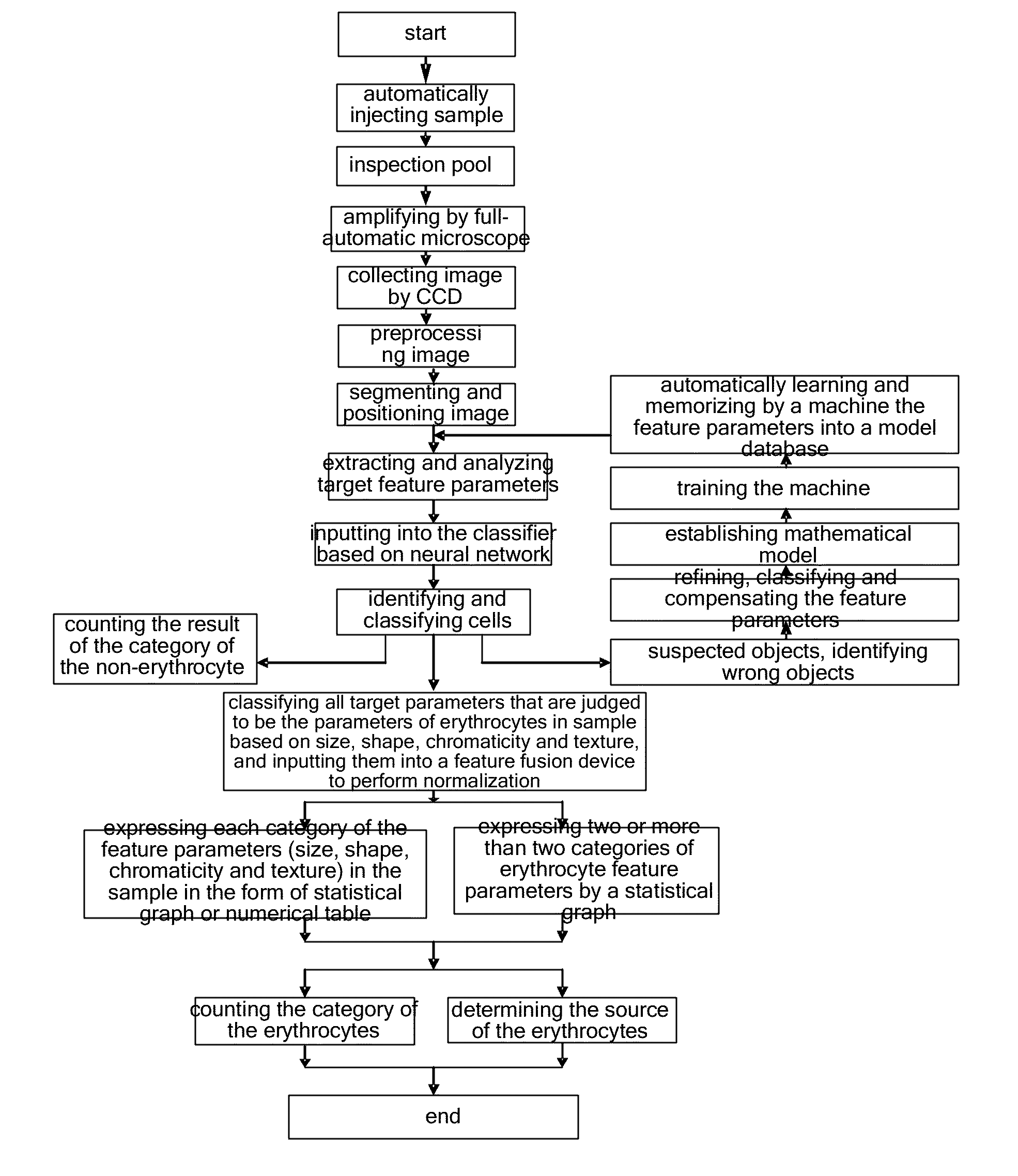
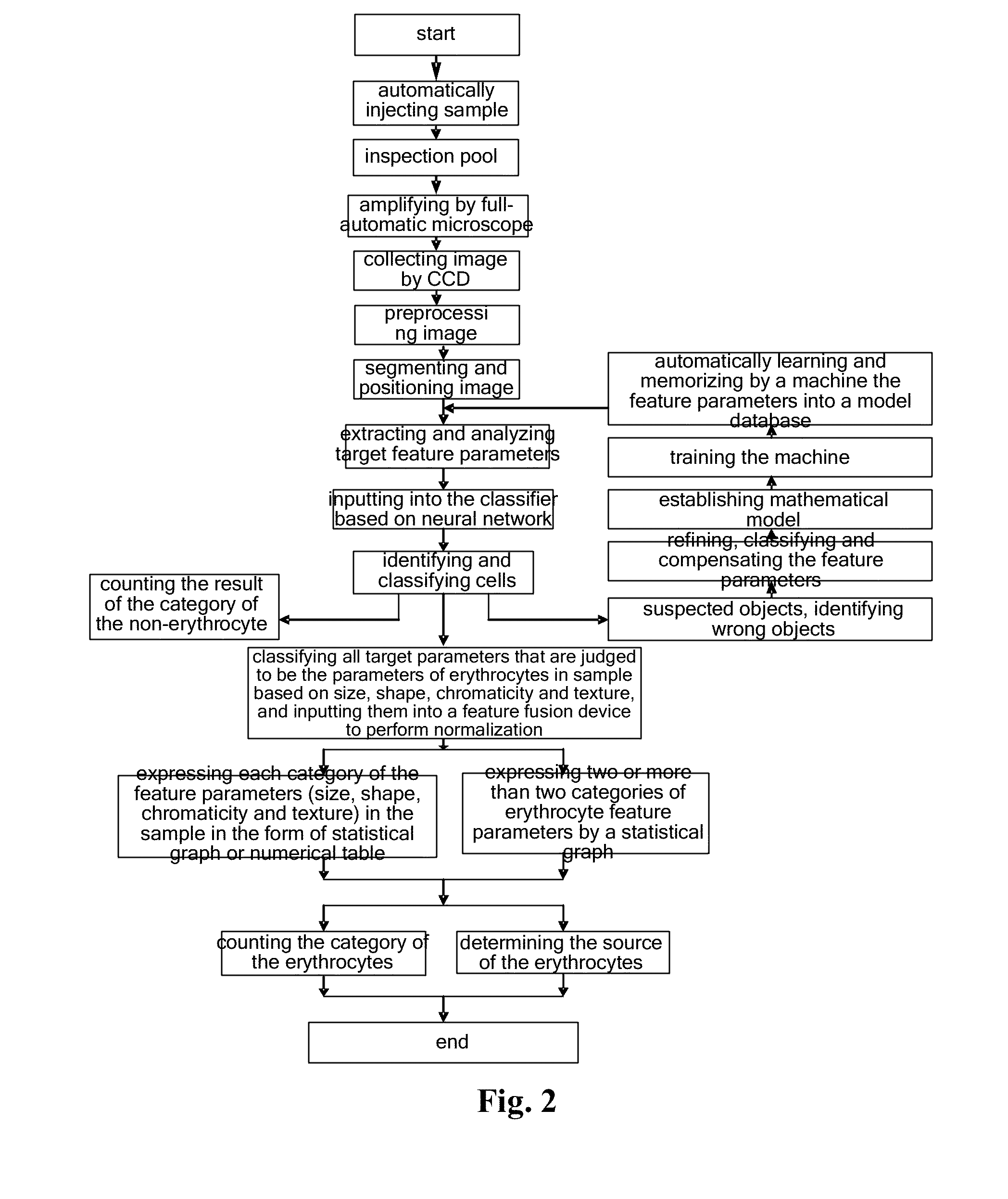
The patent describes a method for analyzing the morphology of red blood cells in a sample, such as blood or urine. The method involves collecting images of cells, processing them to obtain feature parameters, and inputting these parameters into a classifier to identify different types of red blood cells. The method also includes normalizing the feature parameters, performing statistical analysis on them, and expressing the results in a clear and organized format. This method can help to identify the source and properties of the red blood cells, even if there are errors in the identification process. Overall, this method provides a more accurate and reliable way to analyze red blood cells and their sources in samples.

Problems solved by technology

However, the method of the artificial microscopy causes a heavy workload for workers, and the error judgment can be easily caused due to fatigue, and patient's diagnosis may be delayed due to low working efficiency and slow working speed.

Method used


Image

  • Device and Method for Erythrocyte Morphology Analysis
  • Device and Method for Erythrocyte Morphology Analysis
  • Device and Method for Erythrocyte Morphology Analysis

Examples


Embodiment Construction

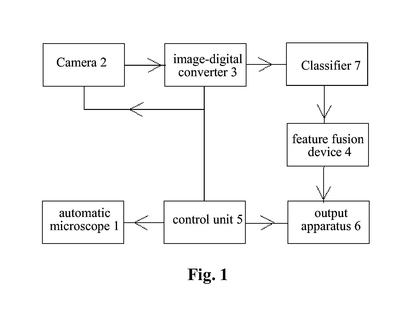
[0063]FIG. 1 is a schematic diagram of a device for performing morphological analysis for erythrocytes according to the disclosure. As shown in FIG. 1, the device for performing morphological analysis for erythrocytes according to the disclosure comprises:

[0064]a. an automatic microscope 1, of which a low-power objective lens is configured to scan a sample (or samples) in a set area at first and to mark a found target area, and meanwhile of which a high-power objective lens is configured to scan the sample(s) in the marked area;

[0065]b. a camera or a CCD element 2, which is configured to collect information of an image of the sample(s) in the marked area;

[0066]c. an image-digital converter 3 for generating digital expression of the image above, wherein the image-digital converter 3 is configured to segment and position cells contained in the image collected at first, and then to digitize the segmented image to extract four types of morphological feature parameters of each of the cel...


PUM

PropertyMeasurementUnit
microscopeaaaaaaaaaa
sizeaaaaaaaaaa
shapeaaaaaaaaaa

Abstract

The disclosure provides a device and a method for performing morphological analysis for erythrocytes, wherein the method for performing morphological analysis for erythrocytes comprises: collecting a morphological image of each of cells in a sample through a Charge Coupled Device (CCD) after amplifying the sample through an automatic microscope; segmenting and positioning the image and extracting target feature parameters after digitizing the image through an image-digital converter; isolating morphological feature parameters of each of the erythrocytes through a classifier established on the basis of the neural network, and normalizing each type of the morphological feature parameters of the erythrocytes through a feature fusion device established on the basis of fuzzy clustering; performing a statistical analysis on each type of normalized parameters obtained or performing a comprehensive statistical analysis according to a plurality of types of parameters, and expressing the result of the statistical analysis or the comprehensive statistical analysis in the form of graph or numerical table, thereby judging whether the morphology of the erythrocyte is normal. The source and property of the erythrocytes can be identified according to the detection for each type of the erythrocytes with the abnormal morphology.

Description

TECHNICAL FIELD OF THE INVENTION[0001]The disclosure relates to a device and a method for performing morphological analysis for erythrocytes in a sample, and in particular to a device and a method for performing morphological analysis for erythrocytes, which is able to automatically identify the type and source of the erythrocytes contained in the sample.BACKGROUND OF THE INVENTION[0002]People have begun to work on a method for counting erythrocytes as early as in 1852, and a counting plate for counting erythrocytes was invented in 1855. An American scientist named W. H. Coulter proposed in 1947 a patent technology which counts particles using a resistance method, and this technology was successfully applied to count the erythrocytes in 1956. With the fast change of science and technology, various ways for detecting the number of erythrocytes emerge constantly. At present, the research and development means applied mainly includes: capacitive mode, photoelectric mode and laser mode,...

Claims


Application Information

Patent Timeline
Patent Type & Authority Applications(United States)
IPC IPC(8): G01N33/50G06K9/00
CPCG01N33/5091G06K9/00147G06K9/0014G01N33/49G01N2015/1493G01N2015/1497G01N2015/011G01N15/1433G06V20/695G06V20/698
Inventor DING, JIANWENZHOU, FENGLIANGLIANG, GUANGMING
Owner CHANGSHA HIGH TECH IND DEV ZONE AVE SCI & TECH IND CO LTD
Learn More