
Shapable bite plates

Active Publication Date: 2014-07-03
ADVANCED ORTHODONTICS & EDUCATION ASSOC LLC
View PDF4 Cites 22 Cited by
  • Summary
  • Abstract
  • Description
  • Claims
  • Application Information

AI Technical Summary

Benefits of technology

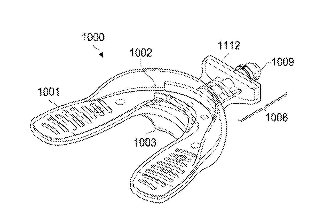
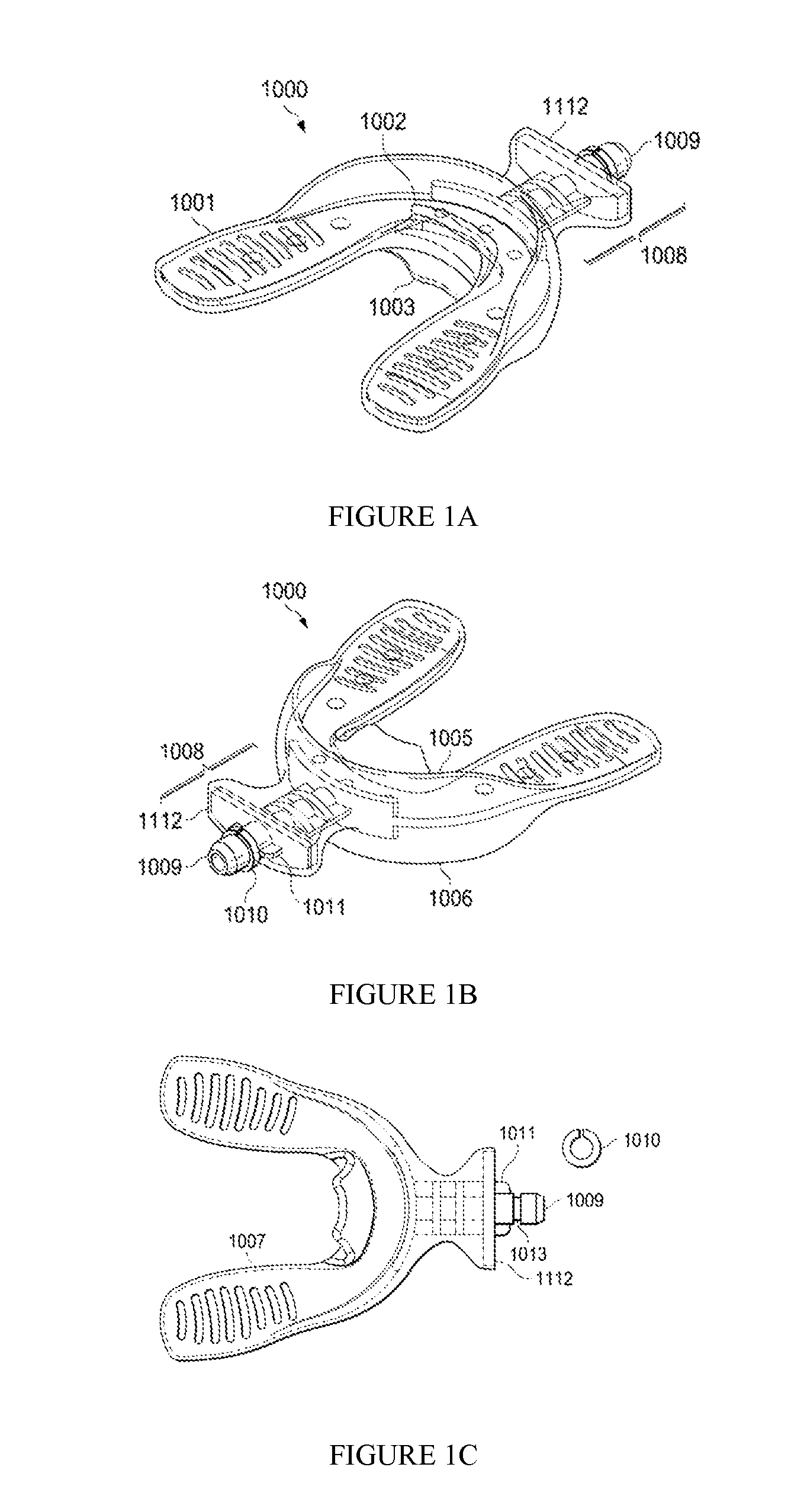
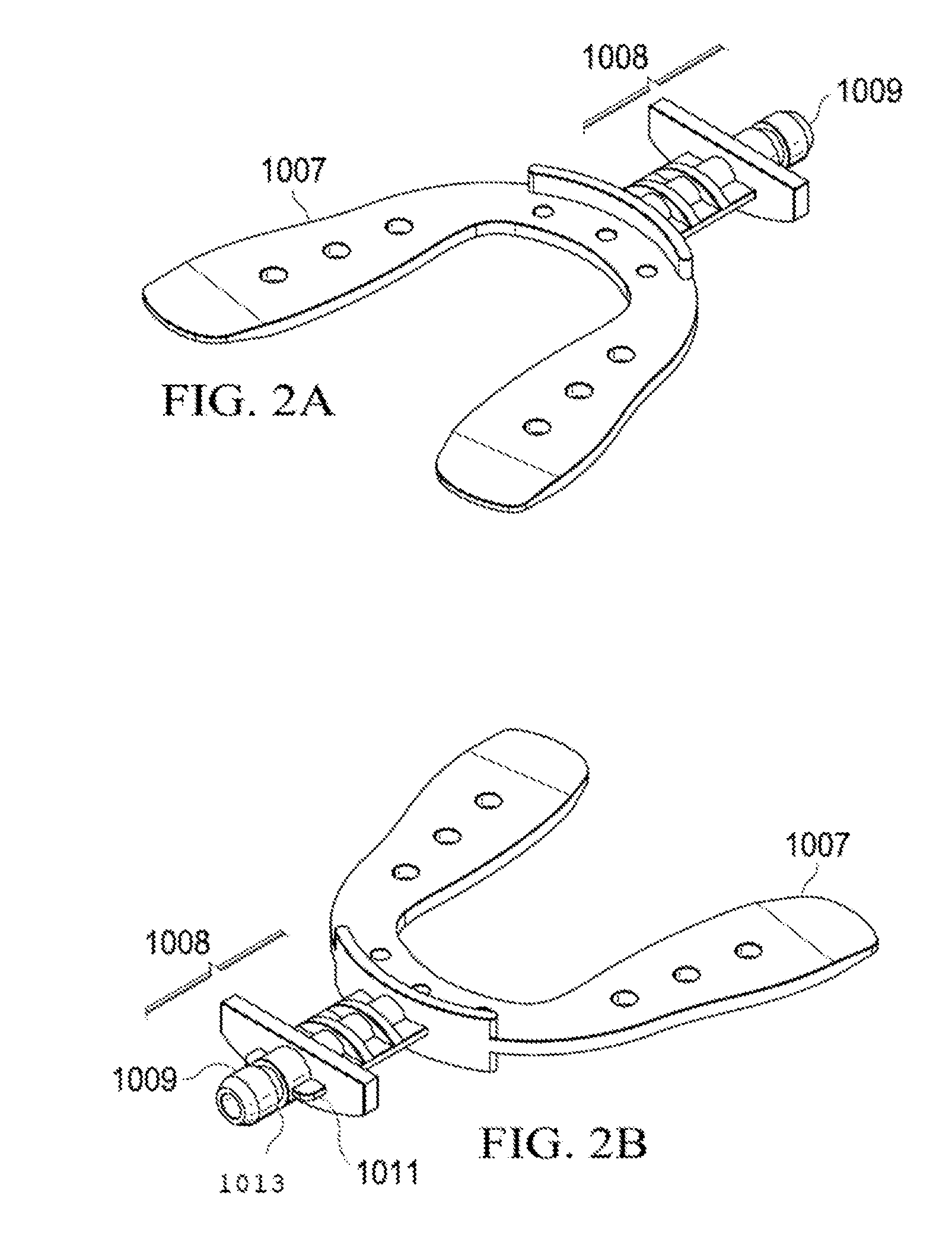
Bite plates used for vibration treatment have a flat and stiff core that can transmit vibration to the mouthpiece and teeth. A shapeable wire can be used to increase the force levels and account for dampening that may occur. The bite plate also has a vertical edge that allows the vibration to be transferred to the teeth in two directions, and keeps the bite plate correctly positioned over the teeth. These improvements make the bite plate more effective and easier to use for vibration treatment.

Problems solved by technology

Treatment with braces is complicated by the fact that it is uncomfortable and / or painful for patients, and the orthodontic appliances are perceived as unaesthetic, all of which creates considerable resistance to use.
Additionally, the 2 year treatment time is very long and cannot be shortened by increasing the force, since too high a force is both painful and leads to tooth resorption.
However, this idea did not become practical until the advent of 3D scanning and computer modeling in 1997, when the Invisalign® system was introduced by Align Technologies®.
The early Mao studies provided a basis for both possible efficacy and likely safety for using vibration in humans to assist orthodontic tooth movement, but the animal studies needed to be repeatable in humans, and the devices used by Mao and the others were completely unsuitable for clinical work.
Finally, the device is slim, capable of hands free operation, lacks the bulky head gear of the prior art devices, and has optimized force and frequency for orthodontic remodeling.
Although compliance with the AcceleDent® is fairly good, with certain patients compliance is less than satisfactory.
In investigating the basis for non-use, OrthoAccel® discovered that a poorly fitting bite plate reduced compliance because the extraoral vibratory source, coupled with a poorly fitting bite plate, resulted in excessive salivation, which tended to egress from the oral cavity.
Patients with poorly fitting bite plates were more likely to have poor compliance records.
Thus, the original devices tend to fit the Asian patient, or patients with the Damon arch (an even wider arch form) less well.
While this solution is one viable option, it requires tooling up and inventory for a substantial number of bite plates, and further still is less than a perfect solution for the wider arches, since it was still based on the Euro arch.
This option, however, requires that inventory be protected from light, and long term stability might be an issue.
Further, once shaped it cannot be reshaped, therefore as treatment progresses new bite plates will be needed.

Method used


Image

  • Shapable bite plates
  • Shapable bite plates
  • Shapable bite plates

Examples


Embodiment Construction

[0071]The disclosure describes a shapeable bite plate, preferably having the characteristics of the special prior art bite plates described in US2008227046, US2008227047, US2010055634, Ser. No. 13 / 609,346, 61 / 624,242, 61 / 615,480 and 61 / 673,236 and intended to be used with intra-oral or extraoral vibratory or other treatment modality sources, as described in the preceding applications for patent, each incorporated by reference in their entireties.

[0072]In some embodiments, a bite plate for an orthodontic remodeling device is provided, said bite plate comprising:[0073](a) a shapeable metal core that is U-shaped in outline to follow the curvature of a dental arch;[0074](b) said metal core covered with a flexible biocompatible polymer;[0075](c) said flexible biocompatible polymer shaped to have an outside edge having upper and lower rims to contact upper and lower facial surfaces of teeth;[0076](d) said flexible biocompatible polymer having an inside edge having optional upper and lower...


PUM


Abstract

Improved shapeable bite plates for use with orthodontic vibratory devices and devices offering other treatment modalities. The shapeable bite plates can be manually shaped to fit the Euro arch, arch form I, the Roth arch, and even widest Damon Arch.

Description

PRIOR RELATED APPLICATIONS[0001]This application claims priority to U.S. Ser. No. 61 / 746,326, filed Dec. 27, 2012, and expressly incorporated by reference herein.FEDERALLY SPONSORED RESEARCH STATEMENT[0002]Not applicable.FIELD OF THE INVENTION[0003]This invention relates to shapeable bite plates that can be used with any device used for orthodontic remodeling.BACKGROUND OF THE INVENTION[0004]A malocclusion is a misalignment of teeth or incorrect relation between the teeth of the two dental arches. The term was coined by Edward Angle—the father of modern orthodontics—as a derivative of occlusion, which refers to the way opposing teeth meet. Angle based his classifications of malocclusions on the relative position of the maxillary first molar. According to Angle, the mesiobuccal cusp of the upper first molar should align with the buccal groove of the mandibular first molar. The teeth should all fit on a line of occlusion, which is a smooth curve through the central fossae and cingulum...

Claims


Application Information

Patent Timeline
IPC IPC(8): A61C7/00
CPCA61C7/008A61C7/08
Inventor VALOIR, TAMSEN
Owner ADVANCED ORTHODONTICS & EDUCATION ASSOC LLC
Learn More