
Solar energy air conditioning system with storage capability

a technology of solar energy and air conditioning system, which is applied in the direction of solar thermal energy generation, refrigerant components, rotary piston liquid engines, etc., can solve the problems of inability to store foods and liquids requiring refrigeration, inability to meet the needs of refrigeration, etc., to achieve the effect of raising the temperature and pressure of the refrigeran

Active Publication Date: 2014-07-10
MUSCATELL RALPH
View PDF13 Cites 20 Cited by
  • Summary
  • Abstract
  • Description
  • Claims
  • Application Information

AI Technical Summary

Benefits of technology

The present invention is a solar air-conditioning system that can operate with concentrated solar heat and solar electric cells / battery, as well as an electric utility grid. The system uses a circulating refrigerant and can store unused BTUs for later use. The evaporator coil is located within a water tank containing an anti-freeze water solution, and the system can also include a separate chilled water system. The refrigerant system includes a supplemental compressor and one-direction positive displacement rotary valves to optimize refrigerant pressures and temperatures. The system can be used in various modes and can also provide refrigeration to areas where electricity is not present.

Problems solved by technology

Additionally, the manufacture of energy at a power plant causes pollution to be released in the air.
Furthermore, electricity availability in undeveloped countries, as well as remote locations in developed countries, may be scarce, on limited basis or often non-existent.
As a result, these locations are unable to store foods and liquids requiring refrigeration due to the lack of electricity.
For undeveloped countries the lack of electricity is a factor in the poverty, hunger and lack of nourishment for its citizens.

Method used


Image

  • Solar energy air conditioning system with storage capability
  • Solar energy air conditioning system with storage capability
  • Solar energy air conditioning system with storage capability

Examples


Embodiment Construction

[0027]While the specification concludes with claims defining the features of the invention that are regarded as novel, it is believed that the invention will be better understood from a consideration of the following description in conjunction with the drawing figures, in which like reference numerals are carried forward. It is to be understood that the disclosed embodiments are merely exemplary of the invention, which can be embodied in various forms.

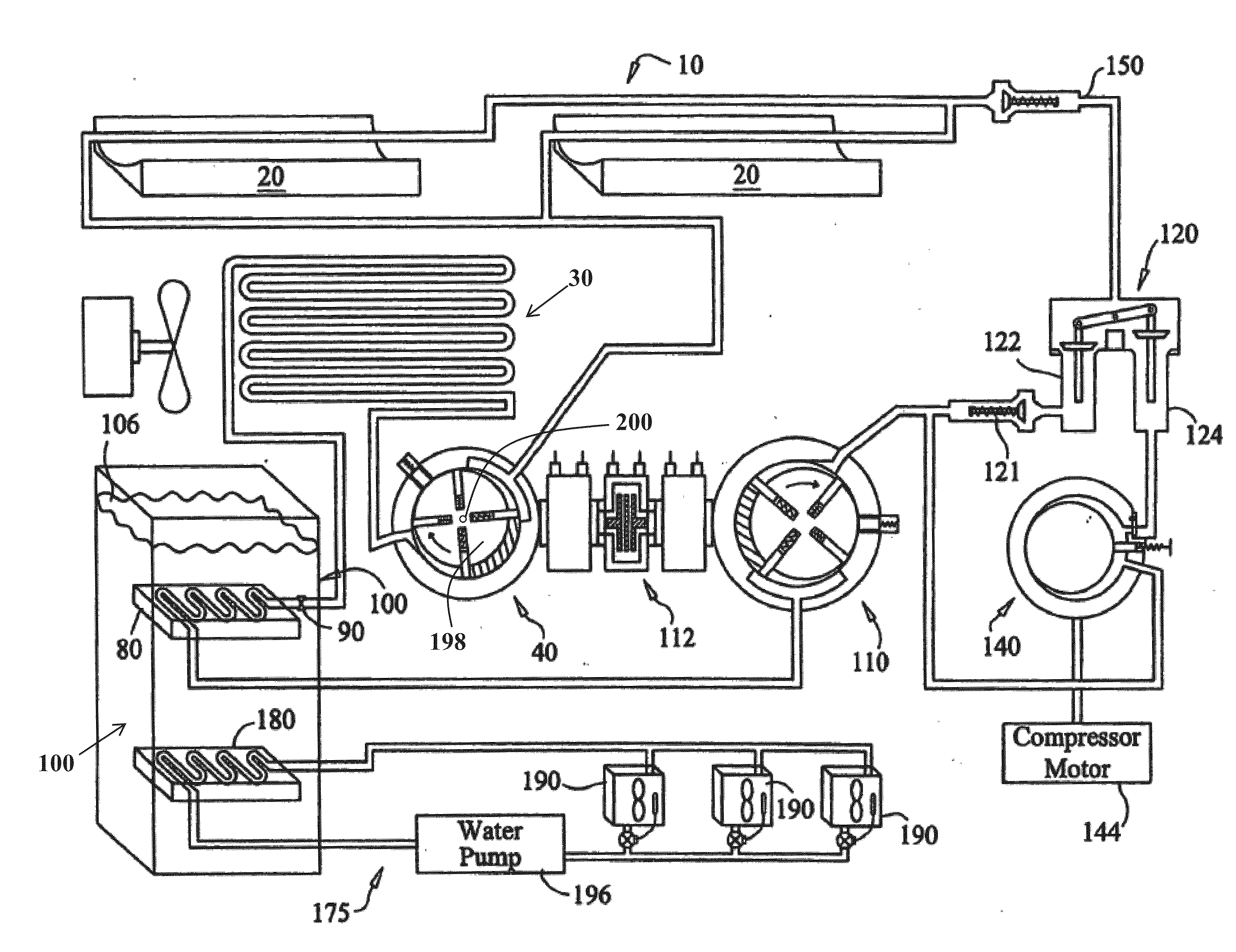
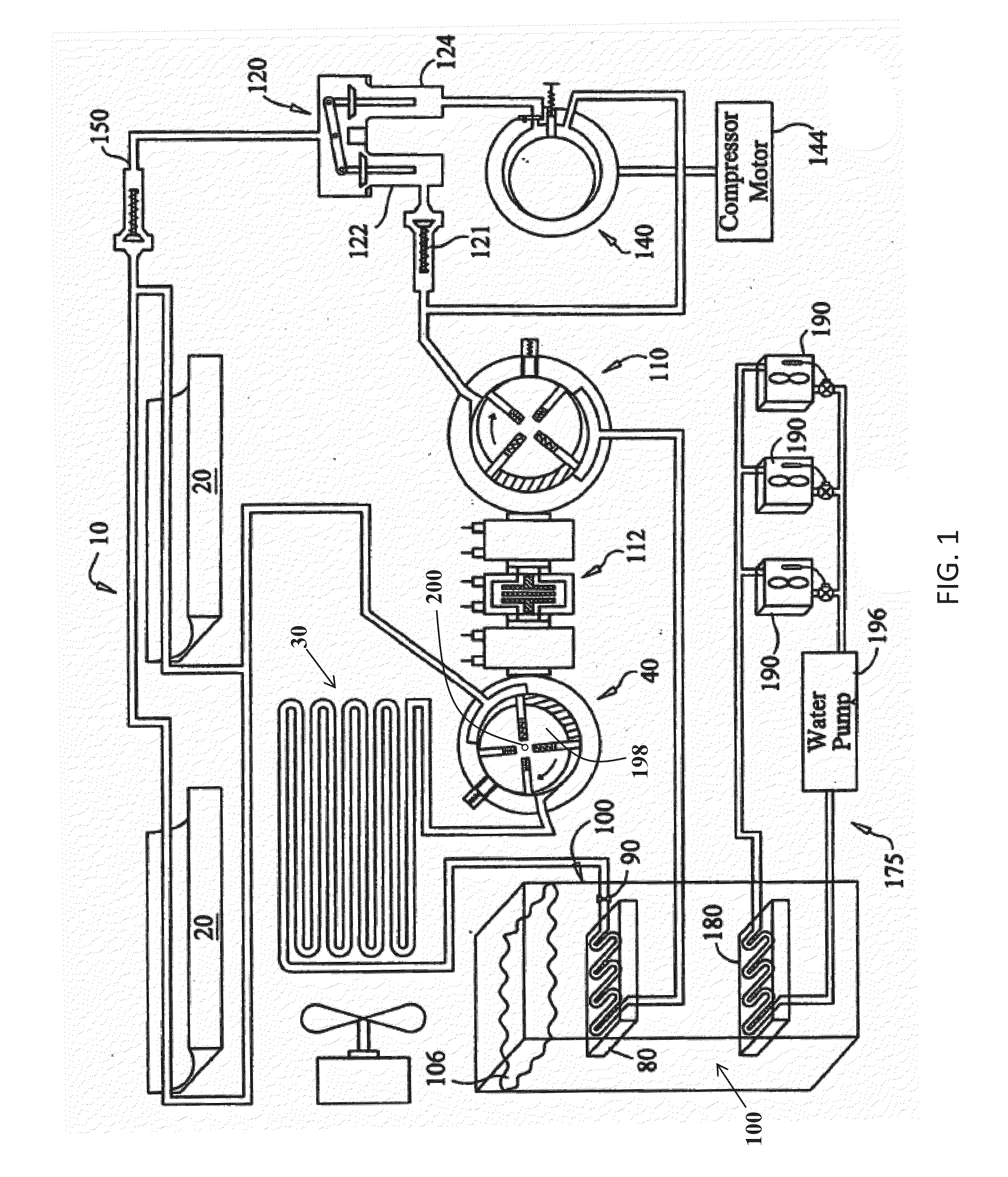
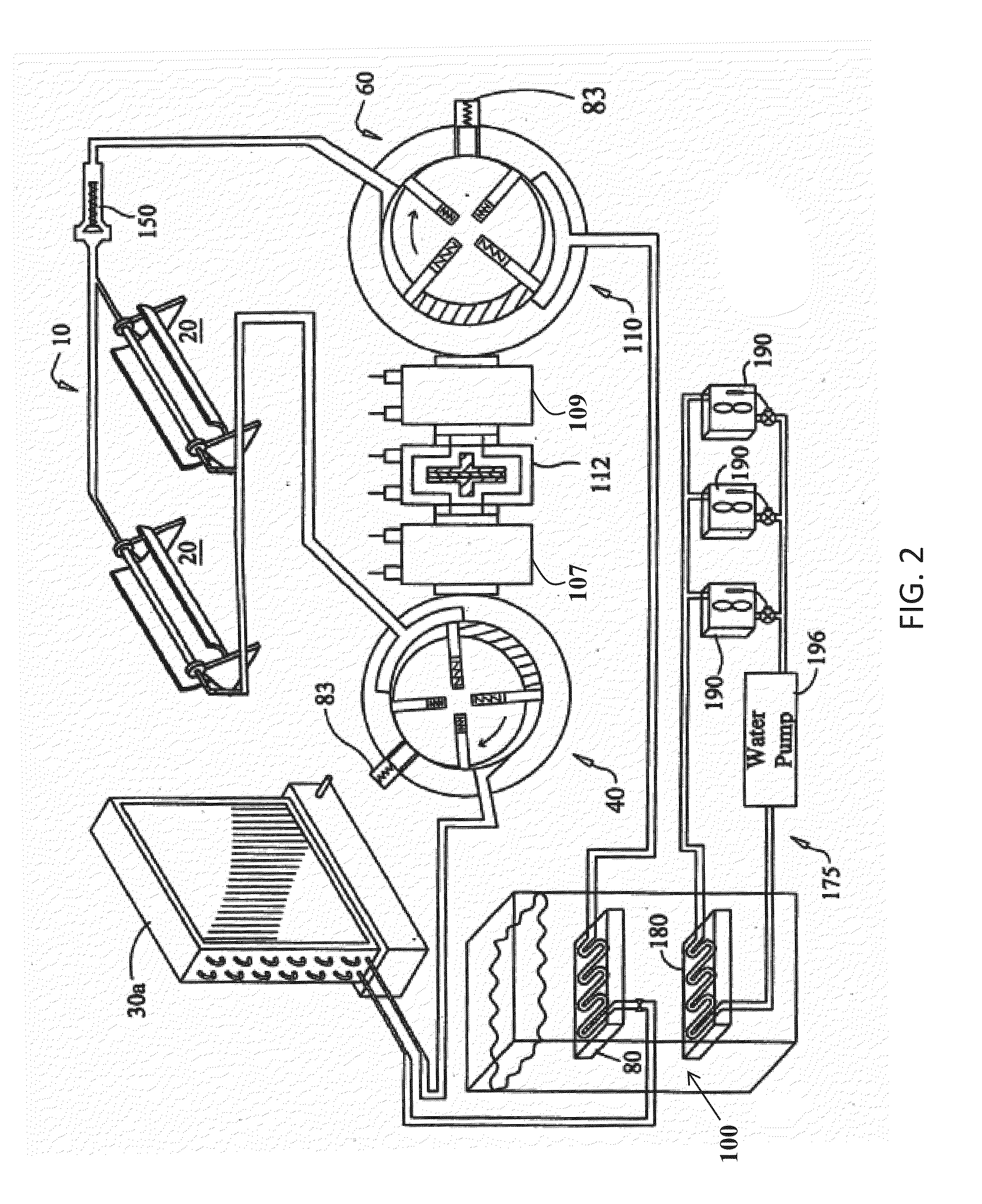
[0028]The present invention provides a novel and efficient solar air-conditioning system, generally referenced as system 10, which can be best seen in FIGS. 2 and 3. In one exemplary embodiment, the system 10 includes one or more solar concentrators 20, 509 preferably a plurality of concentrators 20, arranged in a parallel configuration or in communication with each other. The concentrator(s) 20 capture energy from the sun raising the temperature and pressure of the refrigerant within the pipe, tubing, plumbing, conduits, hoses, etc. (...


PUM


Abstract

The invention utilizes concentrated solar energy in a novel air conditioning system which includes storage capabilities. The refrigerant circuit “high” pressure side is comprised of multiple solar concentrators placed between two positive rotary valves. The “low” pressure side is compromised of the evaporator coil with expansion valve. The refrigerant is confined between the two rotary valves. As solar energy is absorbed into the refrigerant, the pressure and temperature rise. The two rotary valves are then caused to rotate. With rotation, the refrigerant is moved through the circuit. The circuit also includes a condenser to give up heat and an evaporator / expansion valve in which temperature drops with the expanding gas. In addition, this system places the evaporator in a water tank. The water is made cold by conduction with the evaporator and serves as a storage medium. All energy absorbed is converted to cold and stored and utilized as required.

Description

FIELD OF THE INVENTION[0001]The present invention relates generally to air conditioning systems and particularly to a solar energy air conditioning systems having storage capability.BACKGROUND OF THE INVENTION[0002]High electricity bills from air conditioning and / or heating use for a dwelling are common and reoccurring. Additionally, the manufacture of energy at a power plant causes pollution to be released in the air. Furthermore, electricity availability in undeveloped countries, as well as remote locations in developed countries, may be scarce, on limited basis or often non-existent. As a result, these locations are unable to store foods and liquids requiring refrigeration due to the lack of electricity. For undeveloped countries the lack of electricity is a factor in the poverty, hunger and lack of nourishment for its citizens. It is to these problems that the present invention is directed.SUMMARY OF THE INVENTION[0003]The present invention generally provides a solar air-conditi...

Claims


Application Information

Patent Timeline
Patent Type & Authority Applications(United States)
IPC IPC(8): F25B27/00F24S23/74F24S90/00
CPCF04C23/001F04C2210/26F24H7/04F24J2/14F24D3/18F25B27/005F25B41/04F28B1/02F28B1/06F25B2400/141F25B27/002F24F5/0021F24F5/0046F24F2005/0064F04C23/02F04C18/3442Y02B10/20Y02E70/30F24D11/0221F24D11/0235F24D2200/11F24D2200/31F28D3/02Y02E10/40Y02B10/40Y02B30/52Y02B10/70Y02A30/272Y02B30/12F24S23/74F24S90/00Y02E60/14F25B41/20F25B41/24
Inventor MUSCATELL, RALPH
Owner MUSCATELL RALPH
Learn More