Bridging structure for signal transmission of touch panel

a technology of bridging structure and touch panel, which is applied in the direction of electronic switching, pulse technique, instruments, etc., can solve the problems of increasing manufacturing accuracy and difficulty, affecting circuit area, and modern electronic devices always tend to be smaller, lighter, thinner and shorter, so as to reduce the quantity of electric contacts connecting, reduce the size of the ffc, and increase the possible arrangement area of electric contacts

Active Publication Date: 2014-07-10
YOUNG FAST OPTOELECTRONICS
View PDF2 Cites 4 Cited by
  • Summary
  • Abstract
  • Description
  • Claims
  • Application Information

AI Technical Summary

Benefits of technology

[0007]An object of the invention is to provide a bridging structure for signal transmission of a touch panel, which effectively reduces the quantity of electric contacts connecting with the flexible flat cable (FFC), shrink the size of the FFC and enlarge the possible arrangement area of the electric contacts. As a result, the assembling stability and accuracy can be increased, the manufacturing difficulty can be receded and the yield rate can be elevated.

Problems solved by technology

However, modern electronic devices always tend to be smaller, lighter, thinner and shorter.
However, this is seriously adverse to the circuit area with the connecting portion because layout of the signal wires will be constricted.
As a result, the manufacturing accuracy and difficulty will be elevated and the yield rate will be receded.
Also, the connection between a shrunk connecting portion and the FFC tends to be unstable or infirm.
This will cause a problem of transmission.
However, a newly developed electronic device usually requires dozens of or even a hundred transmission lines.
The arrangement of '706 is still at risk of line breakage and alignment error.

Method used


Image

  • Bridging structure for signal transmission of touch panel
  • Bridging structure for signal transmission of touch panel
  • Bridging structure for signal transmission of touch panel

Examples


Embodiment Construction

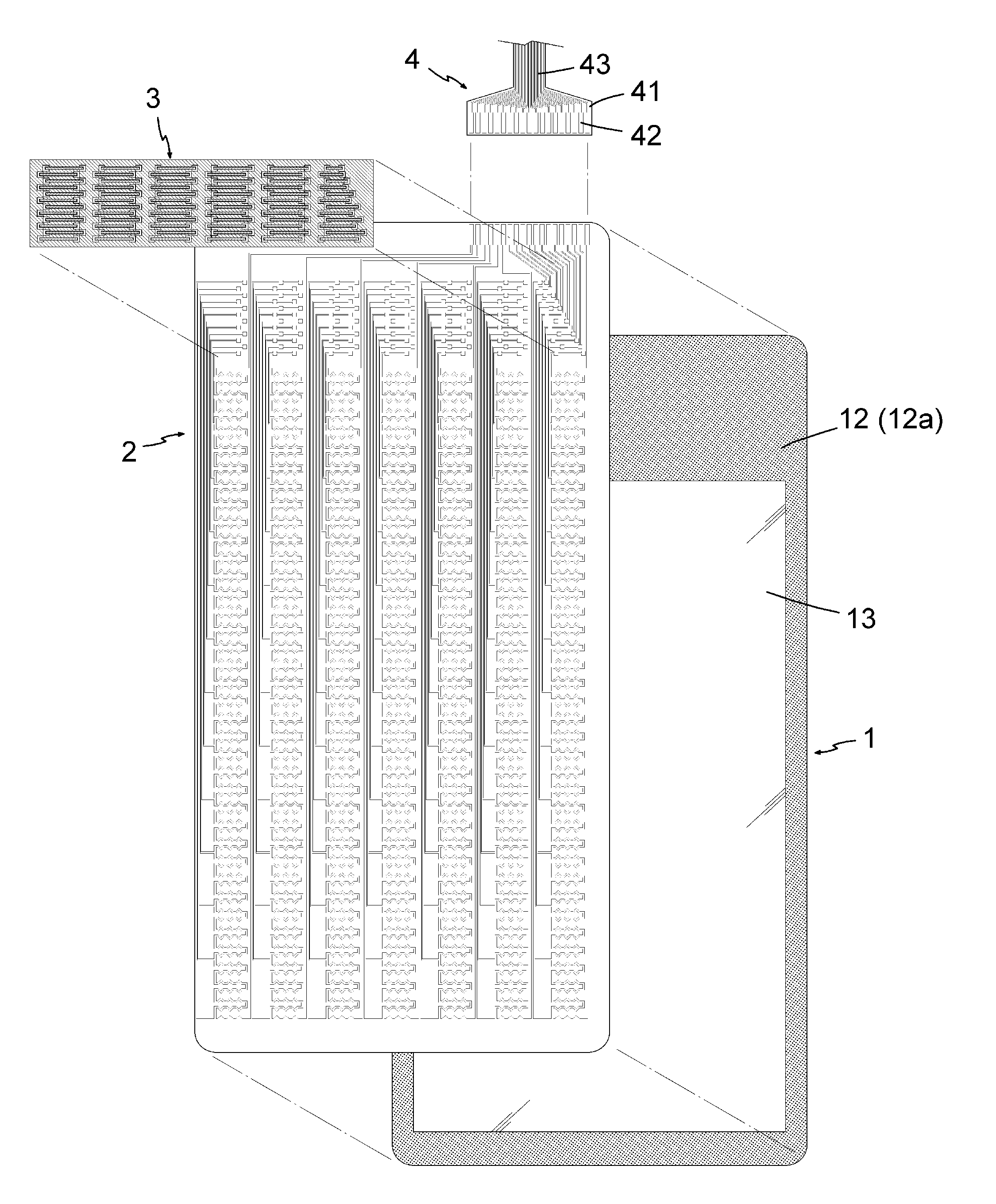
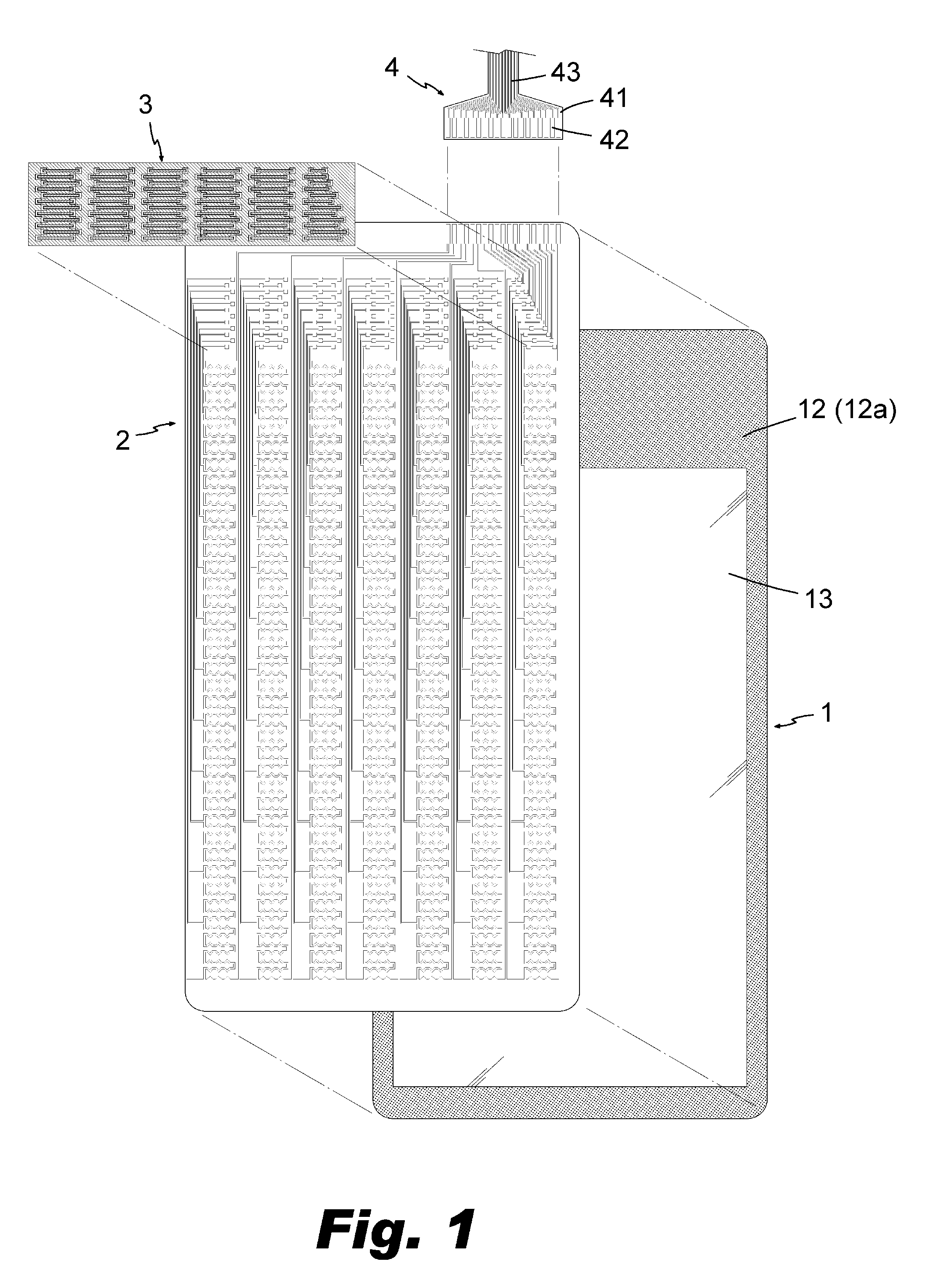
[0019]The invention includes a transparent substrate 1, a transparent touch panel 2, a bridging layer 3 and a flexible flat cable (FFC) 4.

[0020]Please refer to FIGS. 1 and 2. The substrate 1 is a thin sheet with great mechanical strength and is made of, but not limited to, glass, polymethylmethacrylate (PMMA), polycarbonate (PC), polyethylene terephthalate (PET) or cyclic olefin copolymer (COC). A surface of the substrate 1 is provided with a colored periphery 12 which is an opaque film formed by an insulating material. The insulating material may be, but not limited to, ink or photoresist. The opaque film is made by printing or coating and has a thickness of about 15 μm. Usually, width of the colored periphery 12 is less than 3 mm to satisfy the requirement of thin-framed panel. By means of the colored periphery 12, a central visible area 13 and a surrounding shielded area 13 are defined.

[0021]Please refer to FIGS. 3-6. The touch panel 2 is a mutual capacitive touchscreen composed ...


PUM


Abstract

The invention includes a substrate with a visible area and a shielded area, a touch panel overlapped on the substrate and having touch sensor units overlapping with the visible area and a bridging layer with an insulating film. The touch sensor units are connected with signal wires to electric contacts corresponding to the shielded area. The insulating film cloaks the signal wires and electric contacts. The insulating film is formed with through holes corresponding to the electric contacts and is provided with bridging wires between every two adjacent through holes for connecting all of the electric contacts.

Description

BACKGROUND OF THE INVENTION[0001]1. Technical Field[0002]The invention relates to assembling connection between a touch panel and a signal transmission cable.[0003]2. Related Art[0004]A conventional touch panel module includes a transparent substrate and a touch panel overlapping thereon. A central portion of the touch panel is defined as a touch sensing area and its surround is defined as a circuit area. The circuit area is disposed with signal wires connected to the touch sensing area. The circuit area is provided with a connecting portion of an electric contact so that the signal wires can be connected to the electric contacts. The connecting portion is attached to a flexible flat cable (FFC) so as to make electric connection therebetween. As a result, signals from the touch sensing area can be transmitted to a signal processing circuit through the signal wires and FFC.[0005]However, modern electronic devices always tend to be smaller, lighter, thinner and shorter. The structure ...

Claims


Application Information

Patent Timeline
Patent Type & Authority Applications(United States)
IPC IPC(8): H03K17/96
CPCH03K17/9618G06F3/04164G06F3/0443G06F3/0446G06F3/0448G06F3/044
Inventor YANG, KAI-TICHANG, HSING-MING
Owner YOUNG FAST OPTOELECTRONICS
Why Eureka
Try Eureka