Device and Control System for Producing Electrical Power

Inactive Publication Date: 2014-07-10
MAGNETIC MILES LLC
View PDF6 Cites 7 Cited by
  • Summary
  • Abstract
  • Description
  • Claims
  • Application Information

AI Technical Summary

Benefits of technology

[0016]It is yet a further objective of the present invention to provide a power generation system that ut

Problems solved by technology

When the objects are then separated the charge imbalance remains.
Although sunlight is free and abundant, solar electricity is still usually more expensive to produce than large-scale mechanically generated power due to the cost of the panels.
While these devices and systems have met with success in several industries and scientists, the prior art has failed

Method used


Image

  • Device and Control System for Producing Electrical Power
  • Device and Control System for Producing Electrical Power
  • Device and Control System for Producing Electrical Power

Examples


Embodiment Construction

[0033]While the present invention is susceptible of embodiment in various forms, there is shown in the drawings and will hereinafter be described a presently preferred embodiment with the understanding that the present disclosure is to be considered an exemplification of the invention and is not intended to limit the invention to the specific embodiments illustrated.

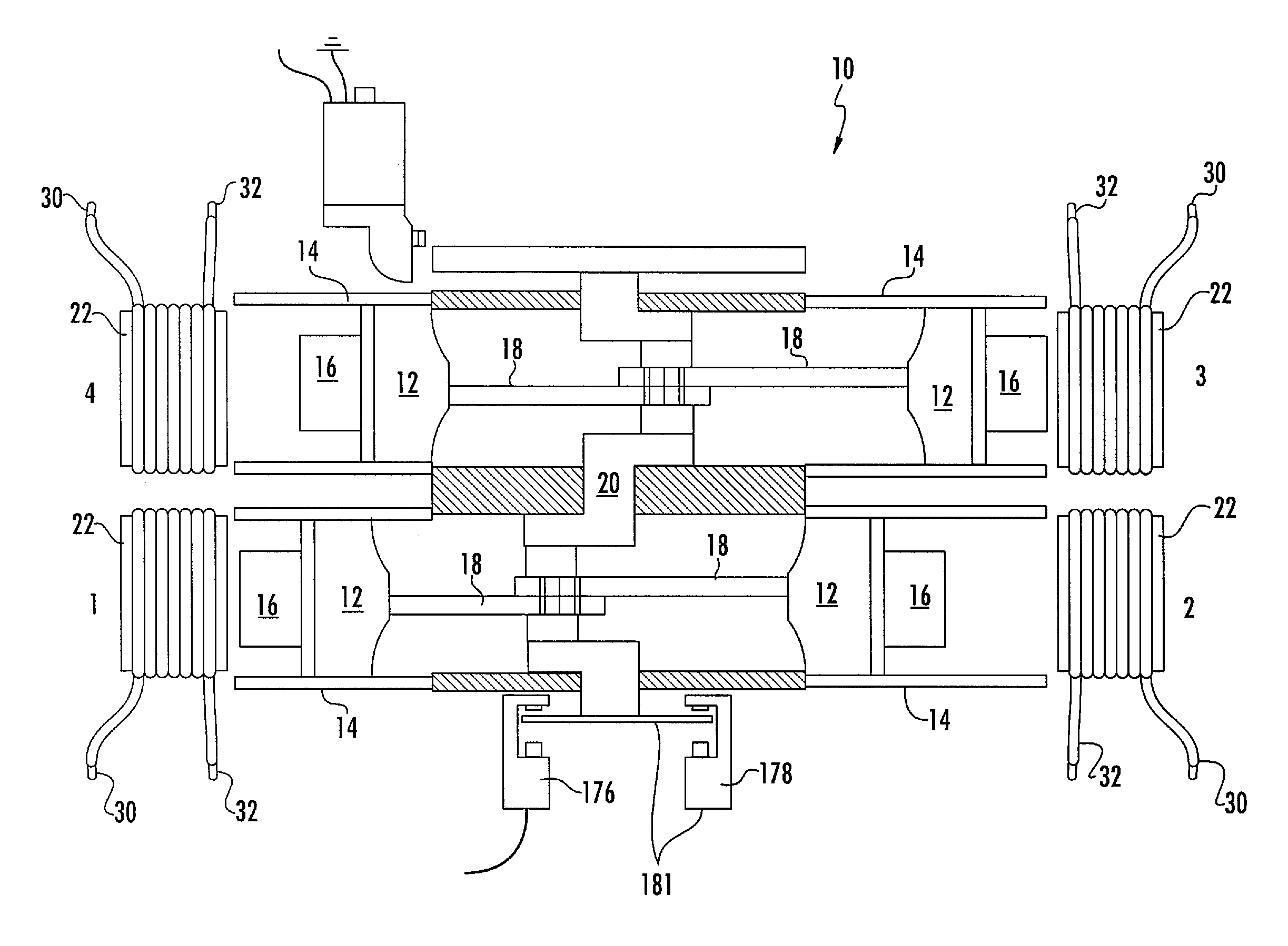
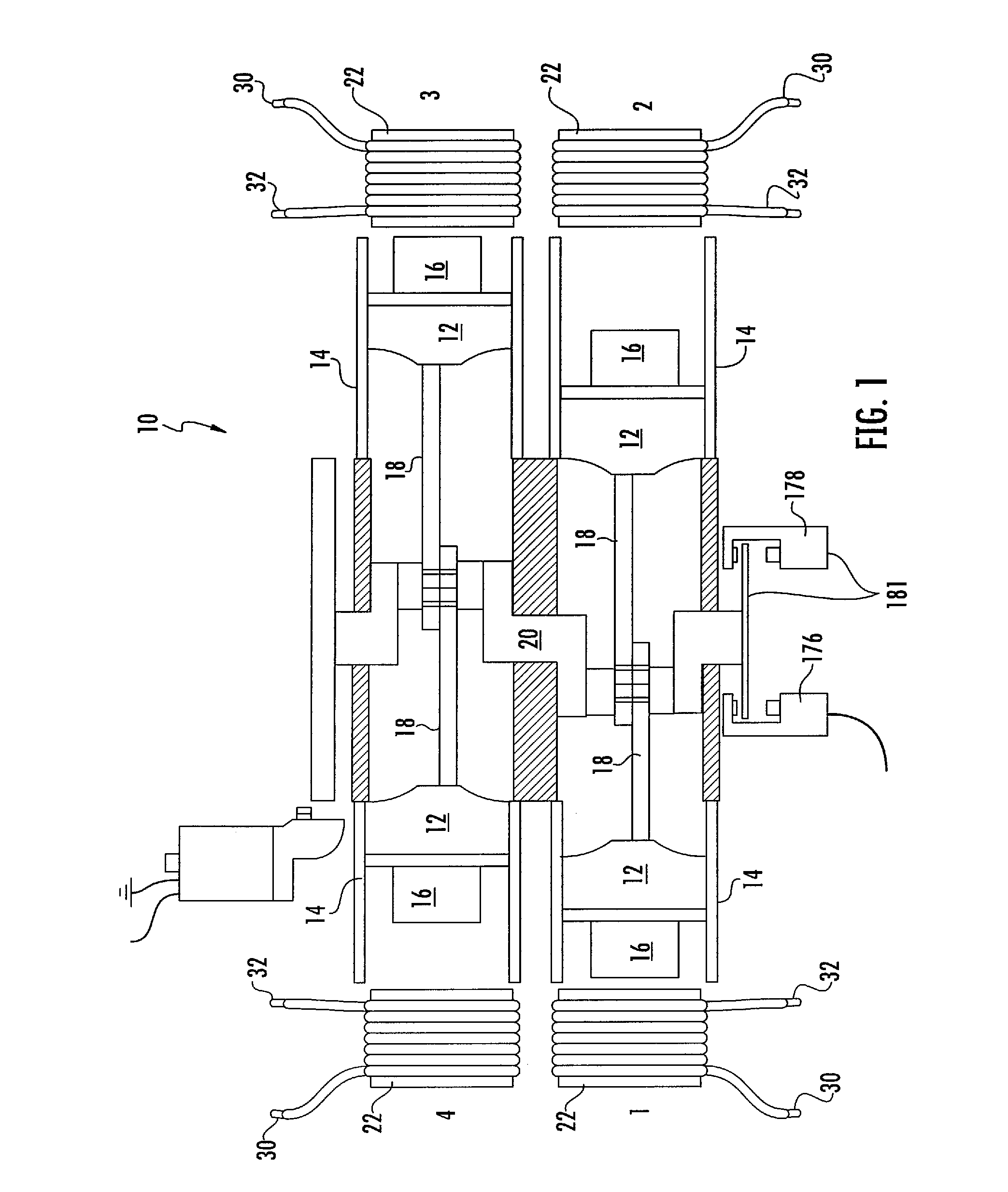
[0034]Referring to FIG. 1, one embodiment of the present power generation system is illustrated in the form of a magnetically operated reciprocating engine 10. The magnetically operated reciprocating engine 10 includes at least one piston 12 constructed and arranged to reciprocate along a substantially linear path illustrated herein as a cylinder 14. The piston 12 includes at least one, and preferably a plurality of permanent magnets 16 secured thereto. The magnets are preferably secured to a top surface of the piston 12 via a non-metallic member or assembly. The piston 12 is pivotally secured to a connecting rod 18 that...


PUM


Abstract

Briefly, the invention involves a system and method for generating electrical power. The system includes an electromagnet positioned with one pole directed toward a like pole of a permanent magnet. The permanent magnet is preferably mounted for oscillating movement toward the pole of the electromagnet. A control system for the electromagnet is provided to supply direct current (DC) power in the form of square wave pulses which coincide with the position of the permanent magnet. Power is collected upon the collapse of the magnetic field within the electromagnetic magnet. In some embodiments the present device is supplied in the form of a reciprocating engine which provides rotary motion in addition to the electrical power generated.

Description

CROSS REFERENCE TO RELATED APPLICATIONS[0001]In accordance with 37 C.F.R. 1.76, a claim of priority is included in an Application Data Sheet filed concurrently herewith. Accordingly, the present invention claims priority to U.S. provisional patent application No. 61 / 748,974, filed Jan. 4, 2013, entitled “Device and Control System for Producing Electrical Power”, which claims priority as a continuation-in-part to U.S. patent application Ser. No. 13 / 454,839, filed Apr. 24, 2012, entitled, “Magnetically Powered Reciprocating Engine And Electromagnet Control System”, which issued May 21, 2013 to U.S. Pat. No. 8,446,112, which is a continuation of U.S. patent application Ser. No. 12 / 701,781, filed Feb. 8, 2010, entitled, “Magnetically Powered Reciprocating Engine And Electromagnet Control System”, which issued May 29, 2012 to U.S. Pat. No. 8,188,690. The contents of each of the above referenced applications are herein incorporated by reference in its entirety.FIELD OF THE INVENTION[0002]...

Claims


Application Information

Patent Timeline
IPC IPC(8): H02K35/02H02K7/075
CPCH02K35/02H02K7/075H02K53/00
Inventor MILES, STEPHENCRISTOFORO, MICHAEL
Owner MAGNETIC MILES LLC
Why Eureka
Try Eureka