Composite probe for plasma diagnosis

A composite probe and plasma technology, applied in the field of plasma diagnosis, can solve problems such as large errors and troubles, and achieve the effects of improving detection accuracy and speed and facilitating debugging.

Inactive Publication Date: 2002-11-20
DALIAN UNIV OF TECH
View PDF0 Cites 46 Cited by
  • Summary
  • Abstract
  • Description
  • Claims
  • Application Information

AI Technical Summary

Problems solved by technology

If two probes are used successively at the same position, it will be more troublesome and the error will be larger

Method used


Image

  • Composite probe for plasma diagnosis
  • Composite probe for plasma diagnosis
  • Composite probe for plasma diagnosis

Examples


Embodiment Construction

[0016] Embodiments of the present invention will be described in detail below in conjunction with the accompanying drawings.

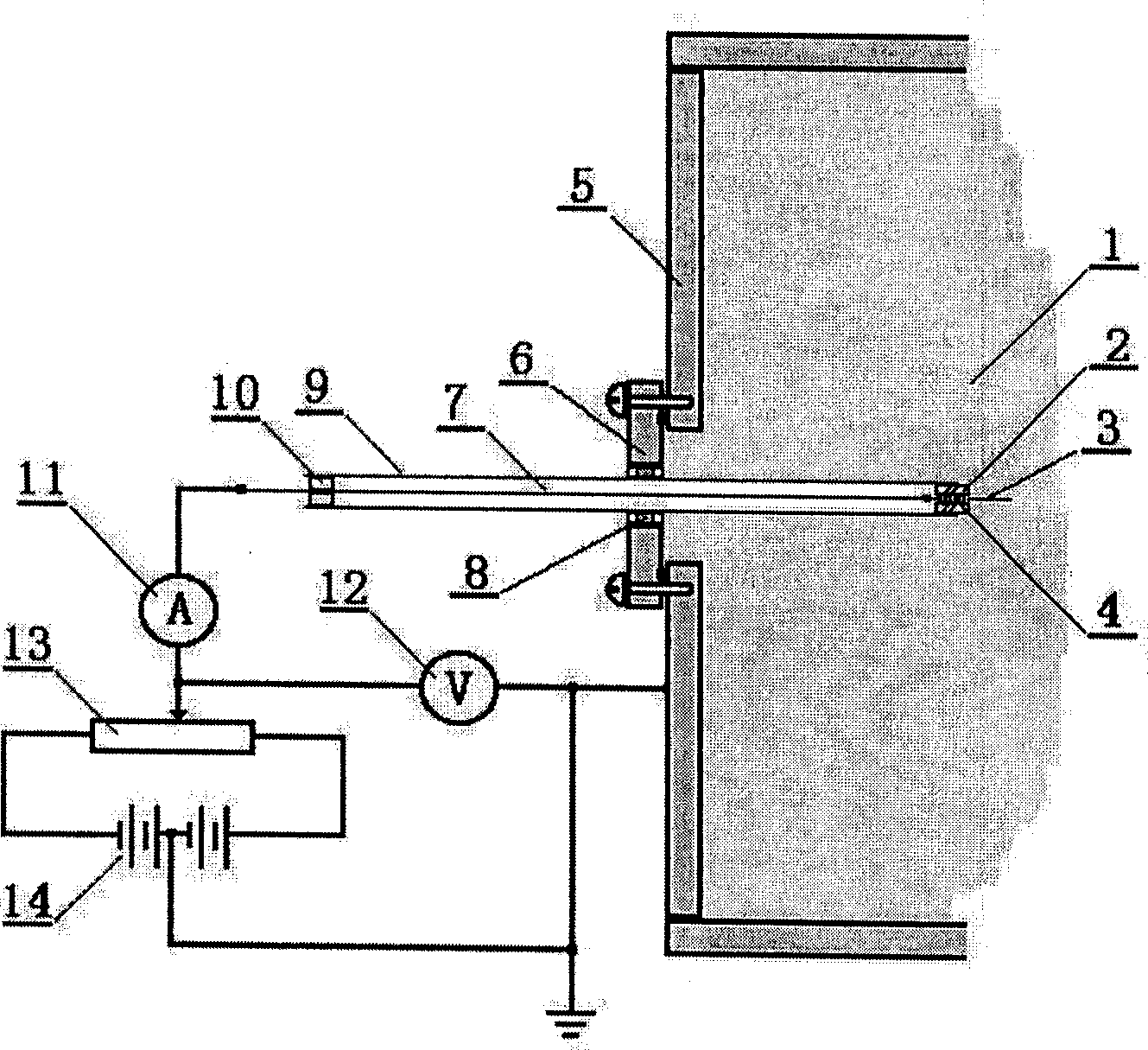
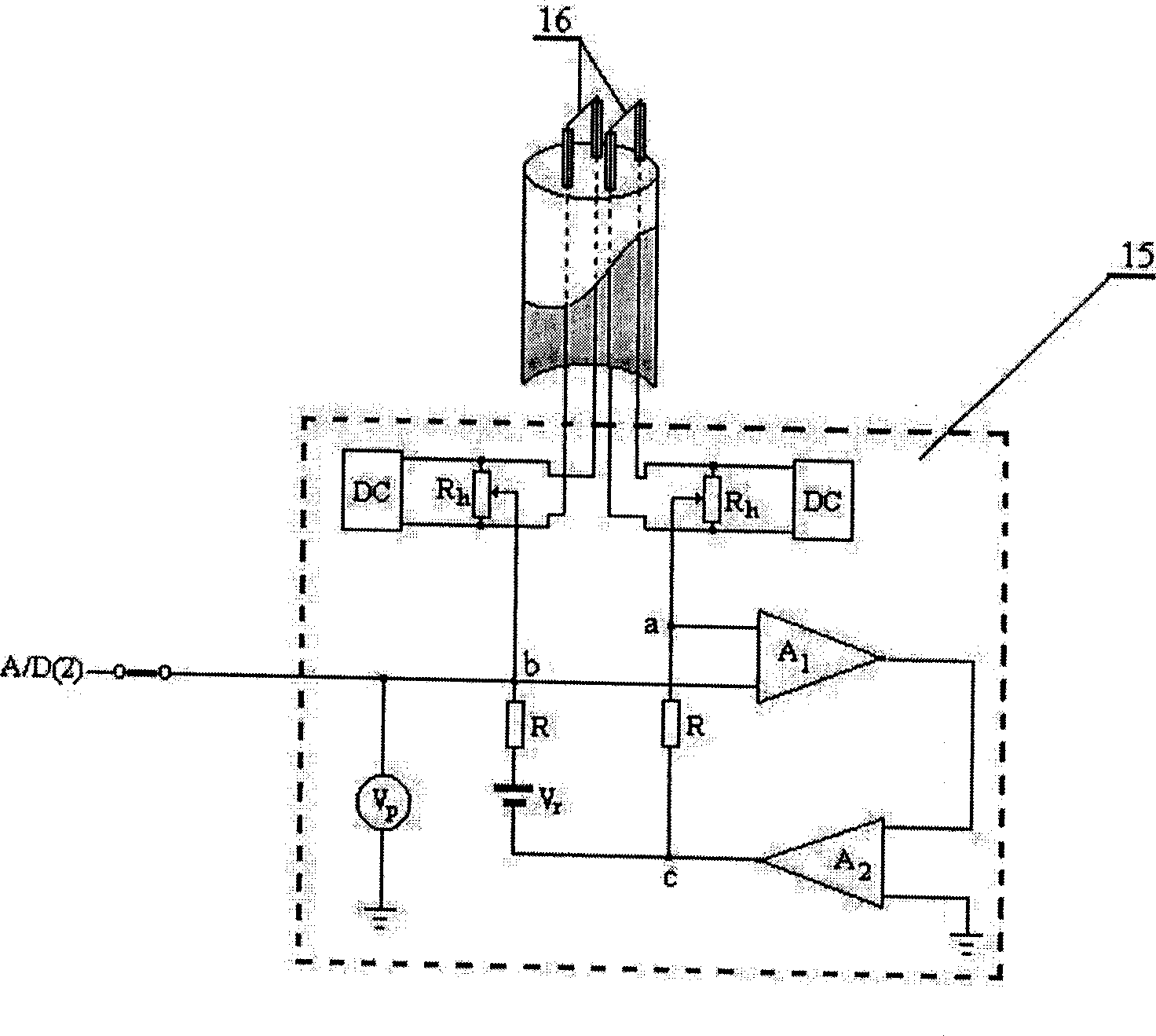
[0017] as attached Figure 4 , the composite probe is to simultaneously load the single probe (3) and the differential emission probe (16) in a probe tube. The composite probe circuit includes a single probe scanning circuit, a differential emission probe space potential tracking circuit (15), a rectangular wave pulse generating circuit (17) and a computer interface circuit (21). The single-probe scanning circuit further includes a trigger-type sawtooth wave generator (18) with power amplification, an isolated operational amplifier (19), probe voltage dividing sampling resistors R1 and R2, and probe current sampling resistor R3. Here, the isolated operational amplifier (19) converts the probe current signal (ie I×R3) relative to the virtual ground into a signal relative to the laboratory ground, so as to facilitate computer acquisition. S1 to S5 are ...


PUM


Abstract

The new type compound probe is used to measure the parameter of plasma in high accuracy, real time and with certain space resolution, which belongs to the technical area of plasma diagnosis. The character is that installing Langmuir single probe and the difference emission probe into the same probe tube forms the compound probe. Measuring the parameter of plasma in high accuracy and real time is realized by combining following circuits and software. These circuits and software are: Langmuir single probe scanning circuit, the automatic follow circuit of the space electric potential for the difference emission probe, the pulse generating circuit of square wave, computer interface circuit as well as software for automatic collecting and analyzing data.

Description

technical field [0001] The invention belongs to the technical field of plasma diagnosis. It is a new composite probe diagnostic technology based on the combination of Langmuir single probe and differential emission probe, which involves accurate determination, real-time monitoring and space-time distribution measurement of plasma parameters. Background technique [0002] At present, the Langmuir (Langmuir) electrostatic probes used for plasma diagnosis include single probes, double probes, emission probes and differential emission probes. The structure of the single probe is attached figure 1 As shown, the front end (that is, the probe) is a thin metal wire with a high melting point (or a small metal disc, or a small metal ball), which is set in an insulating sleeve (or an inner insulating metal sleeve) The lead wire connects the probe to an adjustable power supply. When in use, place the probe part in the plasma, connect one end of the adjustable power supply to the prob...

Claims


Application Information

Patent Timeline
Patent Type & Authority Applications(China)
IPC IPC(8): G01N27/00G01R29/00H05H1/00
Inventor 邓新绿刘莉莹邓凡陆文琪张家良徐军牟宗信
Owner DALIAN UNIV OF TECH
Why Eureka
Try Eureka