Measurement method for reflectivity of high-reflection mirror

A measurement method and high-mirror technology, applied in the direction of scattering characteristics measurement, testing optical performance, etc., can solve the problems of inconvenient promotion and use, and achieve high reliability, improve measurement accuracy, and high measurement accuracy.

Inactive Publication Date: 2006-07-19
INST OF OPTICS & ELECTRONICS - CHINESE ACAD OF SCI
View PDF1 Cites 45 Cited by
  • Summary
  • Abstract
  • Description
  • Claims
  • Application Information

AI Technical Summary

Problems solved by technology

This method uses the combination of folded cavity and straight cavity to reduce the measurement error caused by gas absorption, scattering and diffraction loss...

Method used


Image

  • Measurement method for reflectivity of high-reflection mirror
  • Measurement method for reflectivity of high-reflection mirror
  • Measurement method for reflectivity of high-reflection mirror

Examples


Embodiment Construction

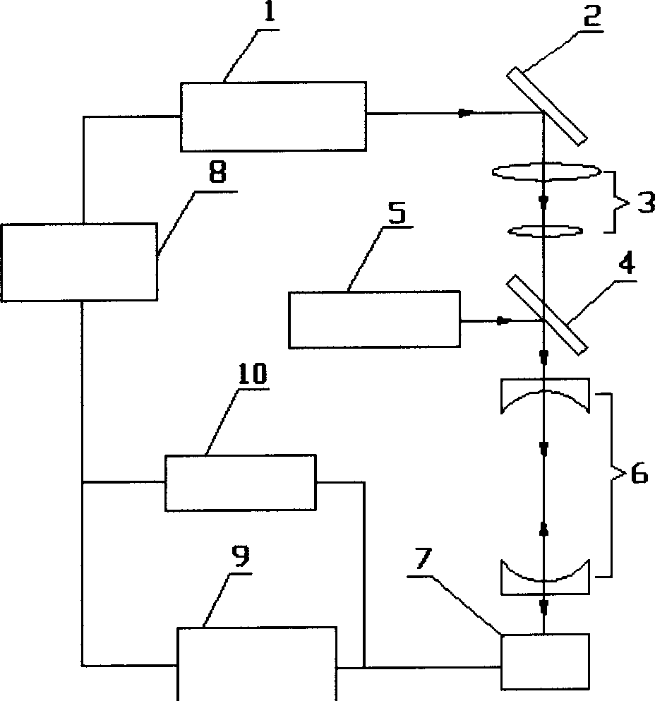
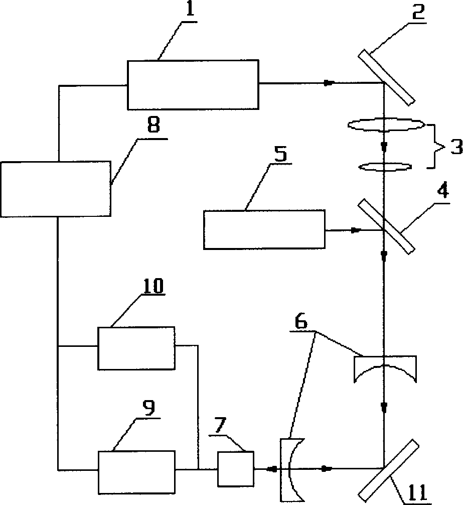
[0024] Such as figure 1 As shown, the measuring device of the present invention consists of a light source 1, a reflector 2, a telescopic system 3, a dichroic beam splitter 4, a helium-neon laser 5, a cavity mirror 6, a detector 7, a function generator 8, a lock-in amplifier 9 and a digital The oscilloscope 10 is composed of a function generator 8 connected to the light source 1 to make the light source square-wave modulated, and simultaneously connected to the lock-in amplifier 9 as a reference signal and the digital oscilloscope 10 as a synchronous trigger signal. The signal output by the detector 6 is simultaneously connected to a lock-in amplifier 9 and a digital oscilloscope 10 to record the amplitude and phase as well as the output waveform of the optical cavity. Such as figure 2 As shown, adding a 45-degree mirror 11 to form a stable folding cavity can measure the reflectivity of any high mirror.

[0025] Light source 1 is a modulated semiconductor laser with a centr...


PUM

PropertyMeasurementUnit
Wavelengthaaaaaaaaaa

Abstract

The invention relates to a method for measuring high reflector reflection index which is characterized in that it adopts square wave or sinusoidal wave modulated wide-spectrum continuous laser as light source which enters into the stable resonator formed by two blocks of high reflectors; it uses square wave to modulate the up stage and down stage of the single period wave to obtain the lasting time and the channel reflecting index or uses fixed phase mode to detect the one-time or odd harmonic of light channel output signal; it uses the amplitude and the phase spiked value to modulate the angle frequency changing curve to obtain the lasting time and the channel reflecting index.

Description

technical field [0001] The invention relates to a method for measuring the parameters of an optical element, in particular to a method for measuring the reflectivity of a high mirror. Background technique [0002] With the continuous improvement of laser power, high-power laser systems have higher and higher requirements for the reflectivity of optical cavity mirrors; with the development of coating technology, the level of coating technology has been continuously improved, and the reflectivity of high mirrors can be coated. It is also getting higher and higher, exceeding 99.9%. In order to accurately evaluate the cavity mirror parameters of the laser and optimize the coating process of the high reflection mirror, it is necessary to accurately measure the reflectivity of the high reflection mirror. [0003] The traditional methods of measuring reflectance, such as spectrophotometer, white light pool, etc., are based on the ratio of measured light intensity, and the error is...

Claims


Application Information

Patent Timeline
IPC IPC(8): G01M11/02G01N21/55
Inventor 李斌成龚元
Owner INST OF OPTICS & ELECTRONICS - CHINESE ACAD OF SCI
Why Eureka
Try Eureka