
Systems and methods of performing duty cycle control

a technology of duty cycle control and system, applied in the direction of pulse manipulation, pulse technique, pulse delivery at different times, etc., can solve the problems of increasing the probability of error, and increasing the probability of duty cycle errors/distortions, so as to facilitate serial communication, reduce data ambiguity, and reduce the probability of error

Active Publication Date: 2005-08-11
TEXAS INSTR INC
View PDF12 Cites 44 Cited by
  • Summary
  • Abstract
  • Description
  • Claims
  • Application Information

AI Technical Summary

Benefits of technology

[0006] The present invention facilitates serial communications by providing systems and methods that perform duty cycle correction in a relatively efficient manner. The duty cycle correction performed can reduce data ambiguity within data boundaries during transmission and reduces a probability of error. The relatively efficient manner employed in the present invention facilitates high speed operation.

Problems solved by technology

Even though HBR clocks provide power advantage over their Full-Baud-Rate (FBR) counterpart, deviation from a desired duty cycle (e.g., fifty percent) increases ambiguity in data boundaries during transmission and re-sampling, and thus increases the probability of error.
Furthermore, as serial communication speeds continue to increase to well over a Gigabit per second, duty cycle errors / distortions can become even more problematic.

Method used


Image

  • Systems and methods of performing duty cycle control
  • Systems and methods of performing duty cycle control
  • Systems and methods of performing duty cycle control

Examples


Embodiment Construction

[0024] The present invention will now be described with respect to the accompanying drawings in which like numbered elements represent like parts. The figures provided herewith and the accompanying description of the figures are merely provided for illustrative purposes. One of ordinary skill in the art should realize, based on the instant description, other implementations and methods for fabricating the devices and structures illustrated in the figures and in the following description.

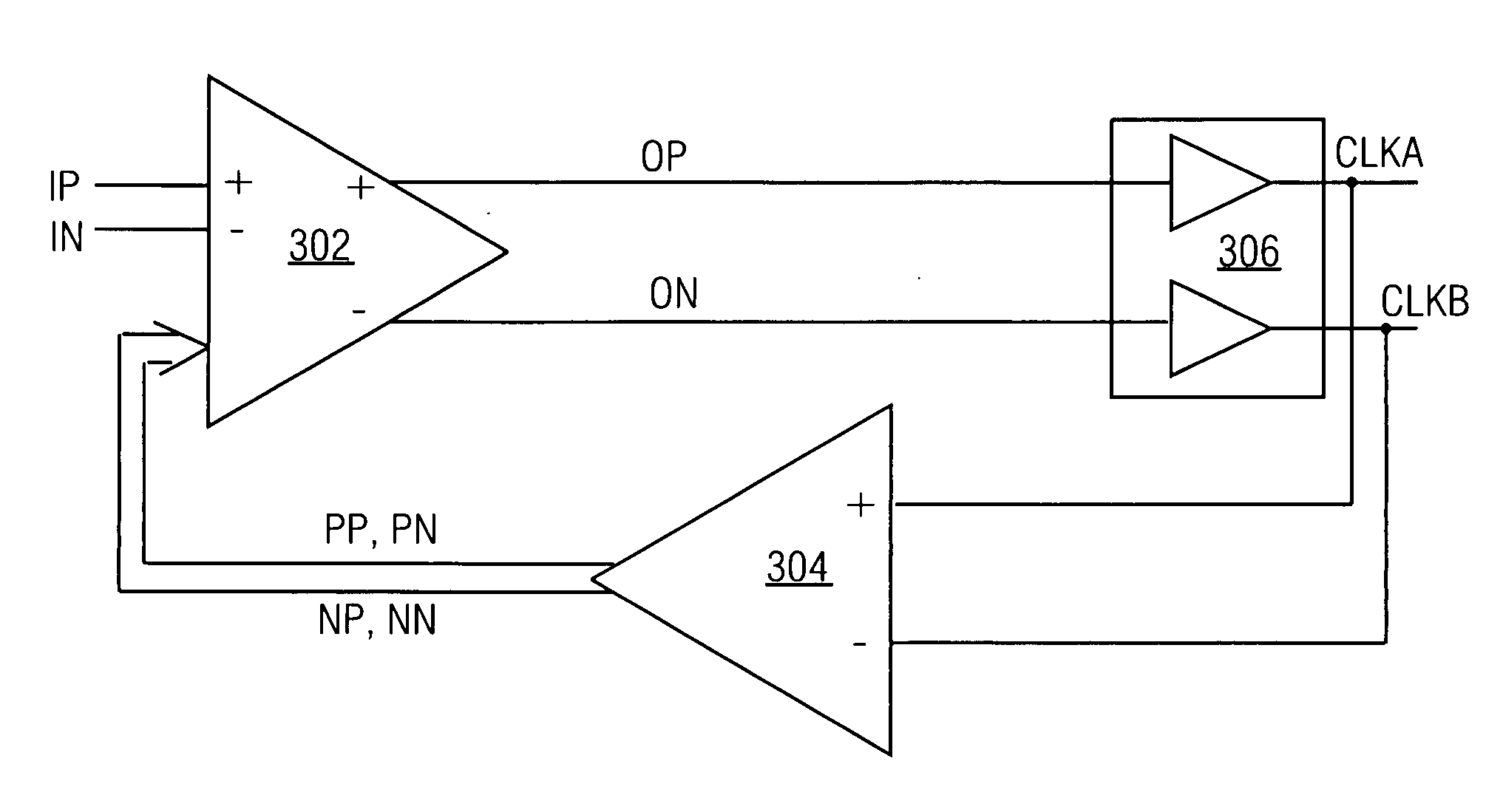
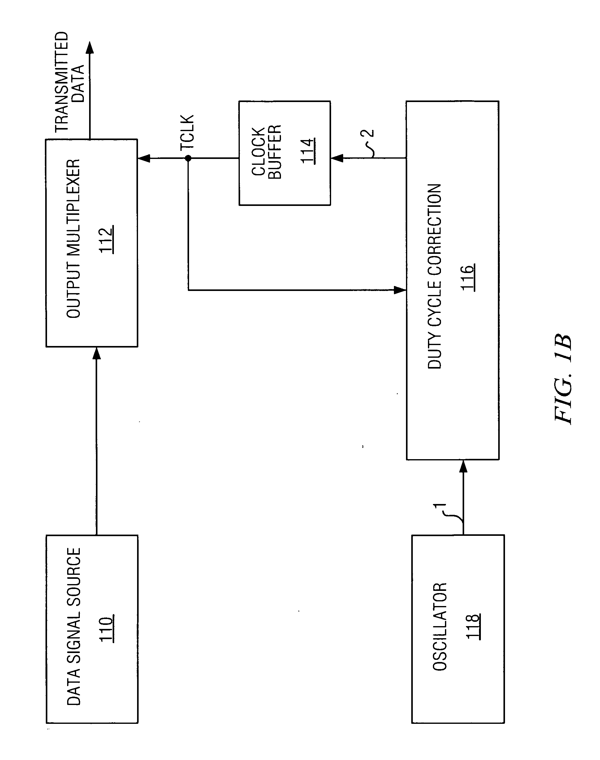
[0025] The present invention facilitates serial communication by providing systems and methods that perform duty cycle corrections during sending / transmitting and receiving. The invention includes a differential to single end converter / amplifier that employs a current starving inverter to appropriately bias and generate clocks signals having a selected / desired duty cycle.

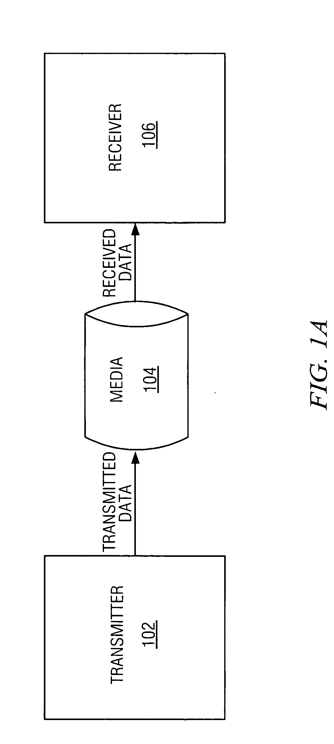
[0026]FIG. 1A is a diagram illustrating a serial communication system in accordance with an aspect of the present invention. The ...


PUM


Abstract

The present invention facilitates serial communication by performing duty cycle correction. A duty cycle correction component 302 performs duty cycle corrections on a pair of differential sinusoidal signals according to a pair of adjustment signals and, as a result, generates a differential pair of square wave signals. A cross coupled buffer 306 buffers the differential pair of square wave signals and provides the buffered signals to a feedback circuit 304 that measures duty cycles of the signals and generates the pair of adjustment signals accordingly. The buffer 306 can also remove skew from the signals. In a transmitter 102, the buffered signals are also generally provided to a multiplexer 112 or encoder and in a receiver 106, the buffered signals are also generally provided to a sampling component 122.

Description

FIELD OF THE INVENTION [0001] The present invention relates generally to high speed serial data communication, and more particularly, to systems and methods that perform duty cycle control of the clock. BACKGROUND OF THE INVENTION [0002] Generally, serial data communication includes a transmitter and a receiver. The transmitter employs one or more internally generated high speed clocks to multiplex the data into a serial data stream that is then placed on a communication media. The serial data stream travels on the communication media and is then obtained from the media by the receiver. The serial data stream is then processed by the receiver in order to recover the original data. The receiver employs one or more internal generated high speed clocks in order to sample and recover the original data. [0003] The duty cycle of these clocks is an important component in reducing timing error induced and maintaining a suitable level of bit error rate (BER) required by some communication st...

Claims


Application Information

Patent Timeline
IPC IPC(8): H03K3/017H03K5/151H03K5/156
CPCH03K5/1565H03K5/151
Inventor WU, LINPAYNE, ROBERT FLOYDLANDMAN, PAUL ERICKIM, WOO JIN
Owner TEXAS INSTR INC
Learn More