
Method and apparatus for effecting synchronous pulse generation for use in variable speed serial communications

a technology of variable speed serial communication and synchronous pulse generation, which is applied in the field of serial communication, can solve the problems of multiple clocks that complicate the testing of system logic, clocks synchronized with usb are unsuitable for other logic that interface, etc., and achieve simplified hardware configuration, simplified hardware configuration, and elimination of phase lock loop circuit of typical serial communication system

Active Publication Date: 2006-11-21
LEXMARK INT INC
View PDF22 Cites 15 Cited by
  • Summary
  • Abstract
  • Description
  • Claims
  • Application Information

AI Technical Summary

Benefits of technology

[0021]An advantage of the invention is that variable speed serial communications is facilitated using a simplified hardware configuration.
[0022]Another advantage of the present invention is that the phase lock loop circuit of a typical serial communications system can be eliminated.
[0023]Still another advantage of the present invention is that the operation of a serial communications standard, that does not transmit a synchronization signal, is facilitated.

Problems solved by technology

In many systems, the clock synchronized with the USB is unsuitable for other logic that interfaces with the USB because the clock rate is slower and the clock frequency or period varies.
Multiple clocks require additional logic for synchronization between the clock domains and multiple clocks complicate the testing of the system logic.

Method used


Image

  • Method and apparatus for effecting synchronous pulse generation for use in variable speed serial communications
  • Method and apparatus for effecting synchronous pulse generation for use in variable speed serial communications
  • Method and apparatus for effecting synchronous pulse generation for use in variable speed serial communications

Examples


Embodiment Construction

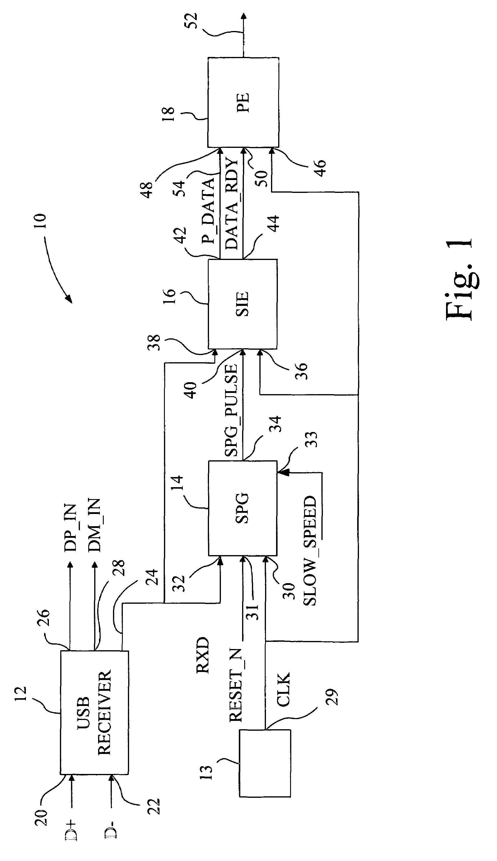
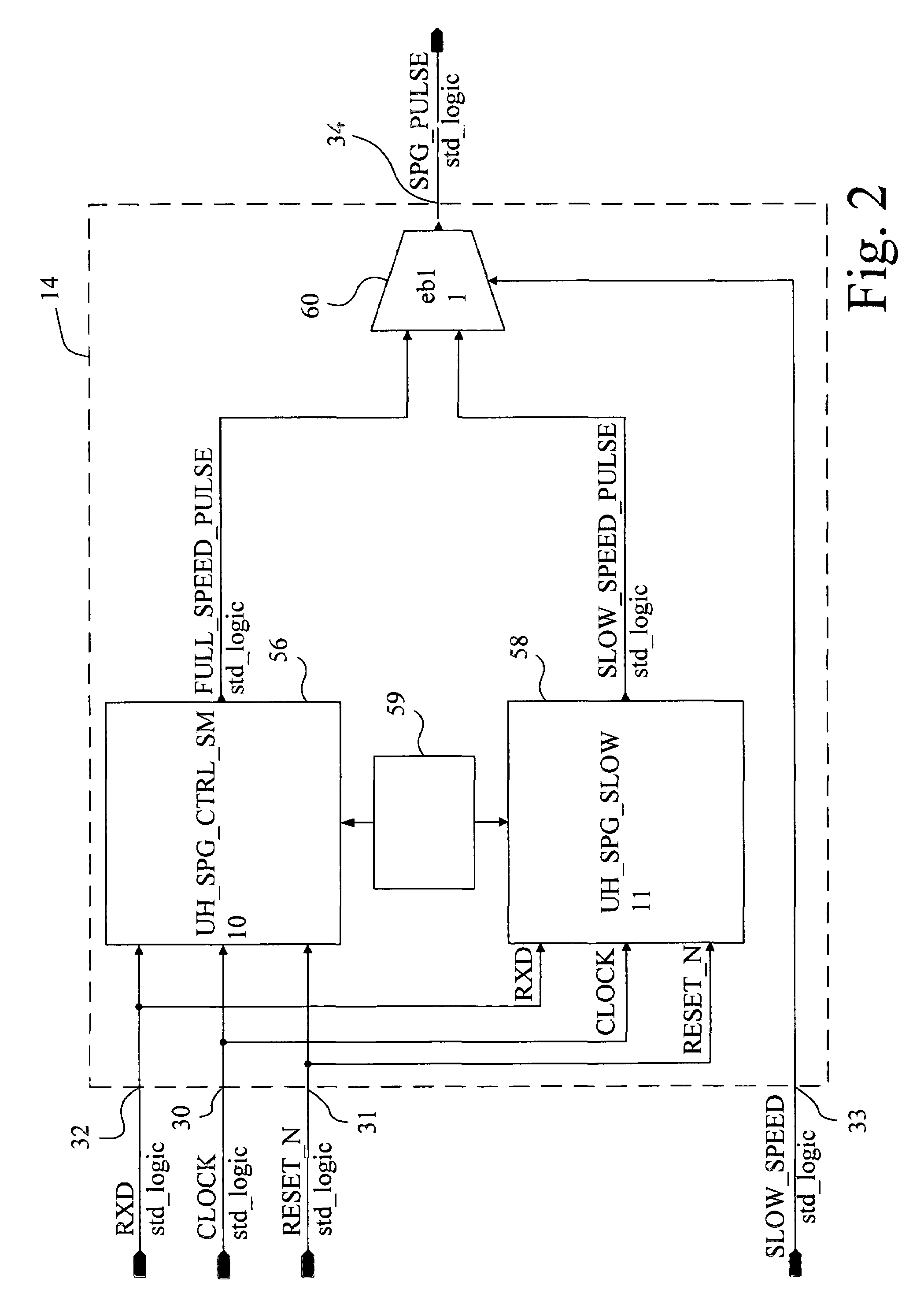
[0035]Referring now to the drawings and particularly to FIG. 1, there is shown a general block diagram of a USB communications device 10 embodying the present invention. For both sending and receiving data, a synchronization pulse is generated to enable the USB sending and receiving logic. However, for sending USB data, synchronization of the data is not necessary because the device or host that is receiving the data is responsible for synchronizing its logic to the transmitted data. Therefore, for sending data, a pulse is generated every 83.3 ns for a 12 MHz operation of the sending logic. Those skilled in the art will recognize that the transmitter portion of USB communications device 10 pertaining to the generation and transmission of data packets using a USB protocol can be implemented using apparatus and methods well known in the art. Thus, for ease of understanding the present invention, the transmitter portion of USB communications device 10 pertaining to the generation and t...


PUM


Abstract

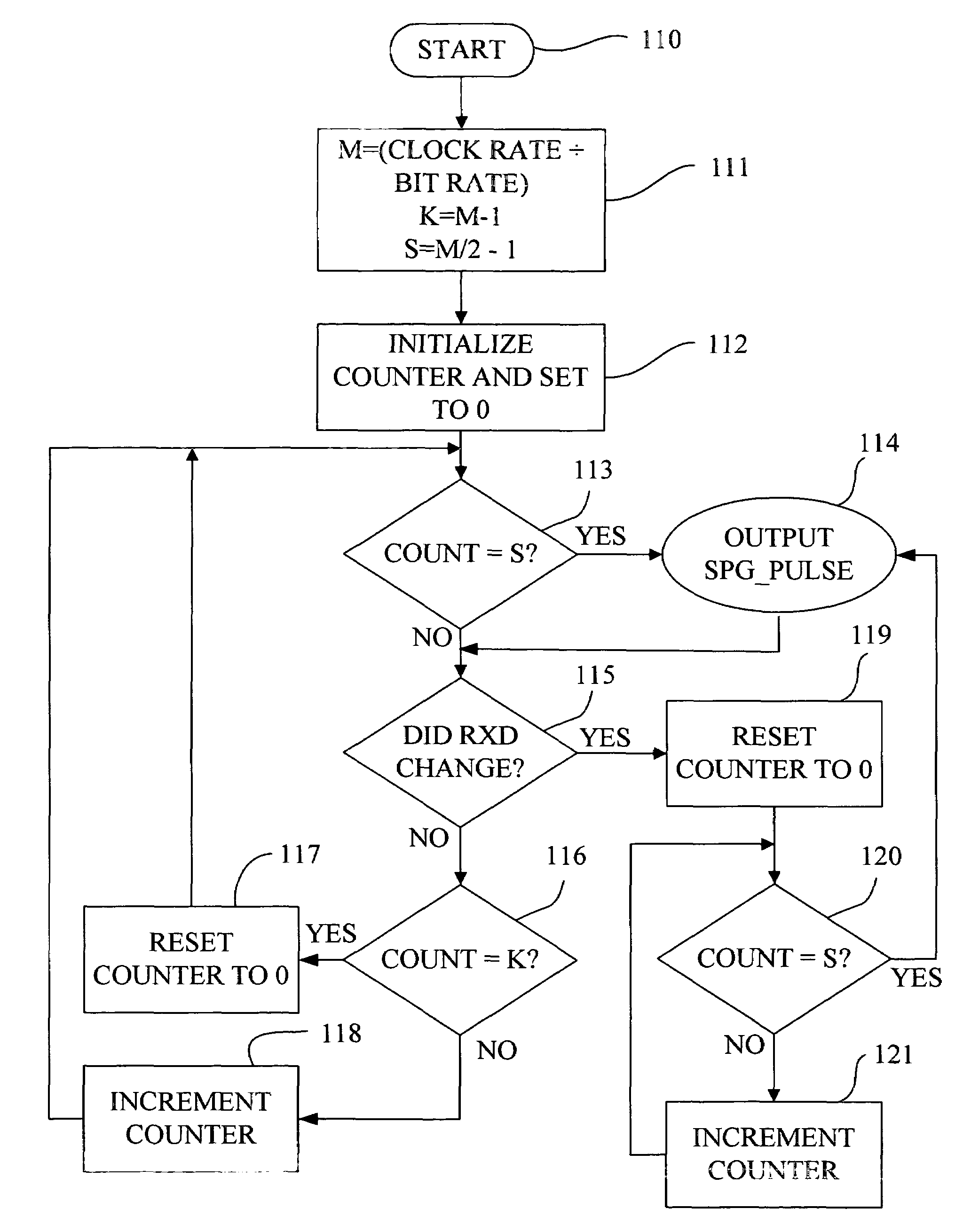
A method for effecting synchronous pulse generation for use in variable speed serial communications is provided. The method includes the steps of obtaining a communication link speed; generating a difference signal representing a signal level difference between at least two data stream signals; providing a clock signal; providing a counter; defining a sample count value of the counter using the communication link speed; incrementing the counter in relation to the clock signal; and determining whether a current count value of the counter corresponds to the sample count value. If the current count value corresponds to the sample count value, then the method performs a step of generating a synchronous pulse. If the current count value does not correspond to the sample count value, then the method performs a step of determining whether a signal level of said difference signal has changed, and if the signal level of the difference signal has changed then performing a step of ignoring further changes in the signal level of the difference signal until the current count value of the counter corresponds to the sample count value at which time the step of generating the synchronous pulse is repeated.

Description

[0001]This is a continuation-in-part of U.S. patent application Ser. No. 09 / 859,782, entitled “METHOD AND APPARATUS FOR EFFECTING SYNCHRONOUS PULSE GENERATION FOR USE IN SERIAL COMMUNICATIONS”, filed May 16, 2001.BACKGROUND OF THE INVENTION[0002]1. Field of the Invention[0003]The present invention relates to serial communications, and, more particularly, to a method and apparatus for effecting synchronous pulse generation for use in variable speed serial communications.[0004]2. Description of the Related Art[0005]A Universal Serial Bus (hereinafter referred to as “USB”) permits a variety of peripheral devices, such as a printer or scanner, to be connected to a generic port in a host computer. During communication between a host computer and peripheral device via a USB, data is transmitted over the bus, but the USB does not transmit a clock for synchronization. Therefore, it is necessary for a USB receiver to have some mechanism to synchronize itself with the incoming data. The USB S...

Claims


Application Information

Patent Timeline
Patent Type & Authority Patents(United States)
IPC IPC(8): H04L7/00H04L7/02H04L7/033
CPCH04L7/0331H04L7/0066
Inventor CRUTCHFIELD, DAVID ALLENRADEMACHER, TIMOTHY JOHNRASCHE, GALEN ARTHUR
Owner LEXMARK INT INC
Learn More