Heater control apparatus

a control apparatus and heater technology, applied in the direction of electrical appliances, electric heating, etc., can solve the problems of insufficient utilization of the power supply capacity of the power supply at every temperature of the resistance heating element, inability to accurately control the temperature of the heater, and inability to fully utilize the power supply etc., to achieve the target temperature more quickly and use the capacity of the power supply

Inactive Publication Date: 2014-07-17
TOYOTA BOSHOKU KK
View PDF3 Cites 8 Cited by
  • Summary
  • Abstract
  • Description
  • Claims
  • Application Information

AI Technical Summary

Benefits of technology

[0019]According to the above configuration, the maximum amount of electric power of the heating element can be supplied at all times irrespective of the temperature thereof by adopting the configuration that the maximum electric power can be supplied to the heating element at the predetermined temperature (an upper limit temperature of the usable temperature range when the temperature coefficient of resistance of the heating element is positive or at a lower limit temperature of the usable temperature range when the temperature coefficient of resistance is negative). Therefore, it is possible to fully utilize the capacity of the power supply irrespective of the temperature of the heating element, and the heating element can be made to reach the target temperature more quickly than with the related-art heater control.

Problems solved by technology

On the other hand, since a capacity of a power supply installed in a vehicle is limited, electric power (electric current) which is supplied to a seat heater needs to be controlled so as to fall within the capacity of the power supply.
As described above, since the resistance value of the resistance heating element changes with change in temperature of the resistance heating element, for example, when the temperature of the heater is controlled with the same duty ratio through the PWM control, the heat generation amount changes as the temperature changes, which causes a problem that the temperature of the heater cannot be controlled accurately.
However, since the amount of electric power supplied to the resistance heating element changes according to the temperature thereof as described above, a problem that the supplying capability of the power supply cannot be fully utilized at every temperature of the resistance heating element.

Method used


Image

  • Heater control apparatus
  • Heater control apparatus
  • Heater control apparatus

Examples


Embodiment Construction

[0028]Hereinafter, referring to the drawings, illustrative embodiments of the present invention will be described in detail.

[0029]Contents described below constitute an example which describes a typical illustrative embodiment of the present invention and are intended to provide an explanation by which the principle and conceptional characteristics of the present invention can be understood most effectively and without any difficulty. In this respect, it is not intended that structural details of the present invention are described more than required for basic understanding of the present invention. Thus, how several forms of the present invention are actually embodied will be appreciated by those skilled in the art with the explanation together with the drawings.

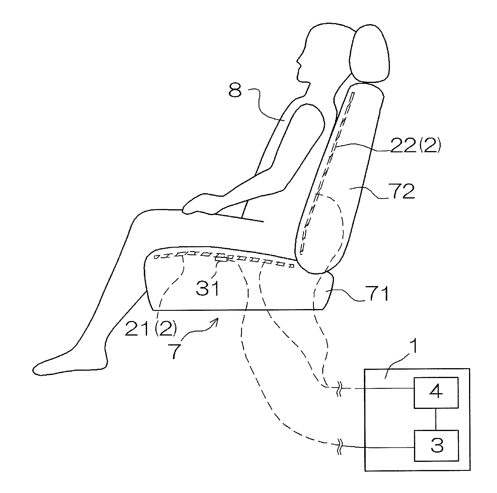
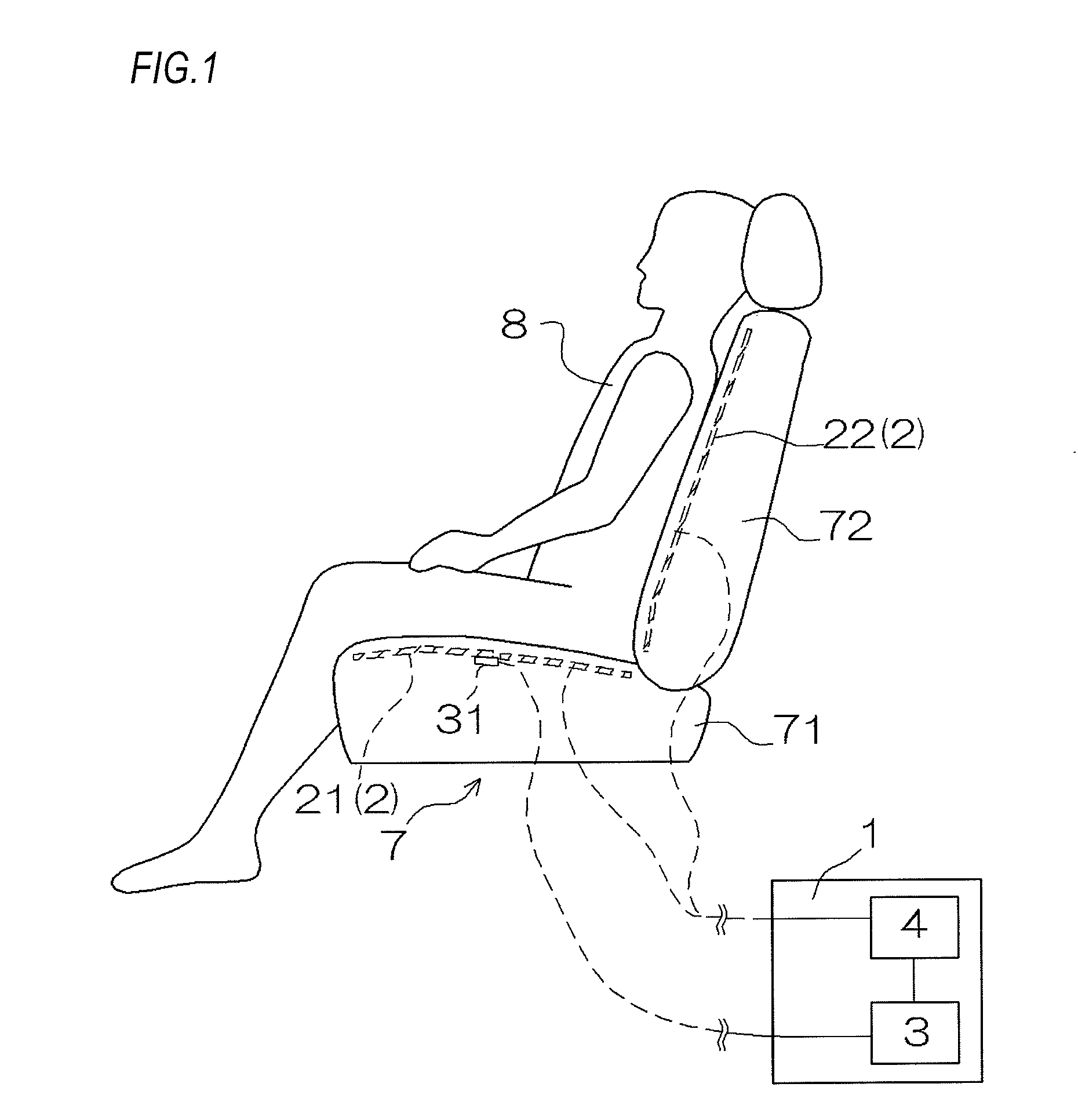
[0030]A heater control apparatus controls temperature of a heater which is provided in a seat by controlling a heat generation amount thereof The heater is configured by a heating element having a positive or negative tempe...


PUM


Abstract

There is provided a heater control apparatus for controlling a heat generation amount of a heater including a heating element which is provided in a seat and which has a positive or negative temperature coefficient of resistance. The heater control apparatus includes a resistance detection unit which detects an electricity amount which corresponds to a resistance value of the heating element, and a control unit which increases or decreases an electric energizing amount supplied to the heating element according to the resistance value obtained by the resistance detection unit.

Description

BACKGROUND OF THE INVENTION[0001]1. Field of the Invention[0002]The present invention relates to a heater control apparatus, and more particularly, to a heater control apparatus which can obtain a constant heat generation amount even though a resistance value of a heating element used in a heater changes and which can fully utilize a capacity of a power supply for supplying electric power to the heater.[0003]2. Description of the Related Art[0004]Conventionally, a seat heater is used in a vehicle such as an automobile to supply warming heat to an occupant thereof. The seat heater includes a heater provided in a seat cushion portion and a backrest of a seat of the vehicle. In the seat heater, the heater is controlled to reach a set temperature by switching on and off power supply of the heater or changing an amount of electric power which is supplied to the heater according to the temperature thereof. For example, the heater is energized continuously until the heater is heated to a s...

Claims


Application Information

Patent Timeline
Patent Type & Authority Applications(United States)
IPC IPC(8): H05B1/02
CPCH05B1/0238
Inventor TAKAHASHI, TSUKASAMIZUNO, KENICHI
Owner TOYOTA BOSHOKU KK
Why Eureka
Try Eureka