Power generation system utilizing circulatory water flow in taper conduit

Inactive Publication Date: 2014-01-23
TENG CHING SHIH
View PDF4 Cites 1 Cited by
  • Summary
  • Abstract
  • Description
  • Claims
  • Application Information

AI Technical Summary

Benefits of technology

The present invention provides a power generator system that uses circulatory water flow in taper conduits, where a small number of pumps are used to incessantly pump up the tail water and then intensify the speed of water flow according to fluid mechanics so as to drive a Pelton wheel power generation system with the high speed jet flow and produce large scale commercially applicable electric power. It can generate electricity from the high speed jet flow using a minimum amount of water resources and can be installed at any location. The system includes a Pelton turbine generator, a pumping up tail water circulation device, and a hp pump. It converts low speed water flow into a high speed jet flow using the principle of fluid mechanics and uses the fluid flow to drive the Pelton turbine generator system to produce electric power. The system achieves the maximum effect with only a small amount of water resources.

Problems solved by technology

The economic and cultural growth of the whole world results in producing a large amount of CO2 which brings about a severe problem of environmental contamination that leads to causing the world improper for all kinds of living creatures to maintain their health.
Another problem is that when the final day of using up petroleum energy comes true, the whole world will get into a mess fighting one another for the energy source.
But it is regretful that the installation for the solar energy requires a large solar cell panel because of its low efficiency resulting in inevitable expensive capital investment and broad installation area that is impossible for every country to try.
The wind power, though it is bestowed upon a higher efficiency, yet it has to face the disadvantages of unstable wind flow and expensive installation cost.
Meanwhile, it should be understood that not all the rivers are suitable for establishing water power plants.
The country who has no sufficient water energy resource can't but seek help for other energy sources.
There is a fatal disadvantage of hydraulic power generation that it requires a big capital investment, technique and time for installation in addition to tedious maintenance work and replacement of equipment in the following days.
Besides, there is an innegligible problem that the damming of water flow may cause a certain damage to the environment so that a careful estimation before establishing a water power plants is very important, otherwise the advantage gained by development of water energy does not pay for its accompanying damages.

Method used


Image

  • Power generation system utilizing circulatory water flow in taper conduit
  • Power generation system utilizing circulatory water flow in taper conduit
  • Power generation system utilizing circulatory water flow in taper conduit

Examples


Embodiment Construction

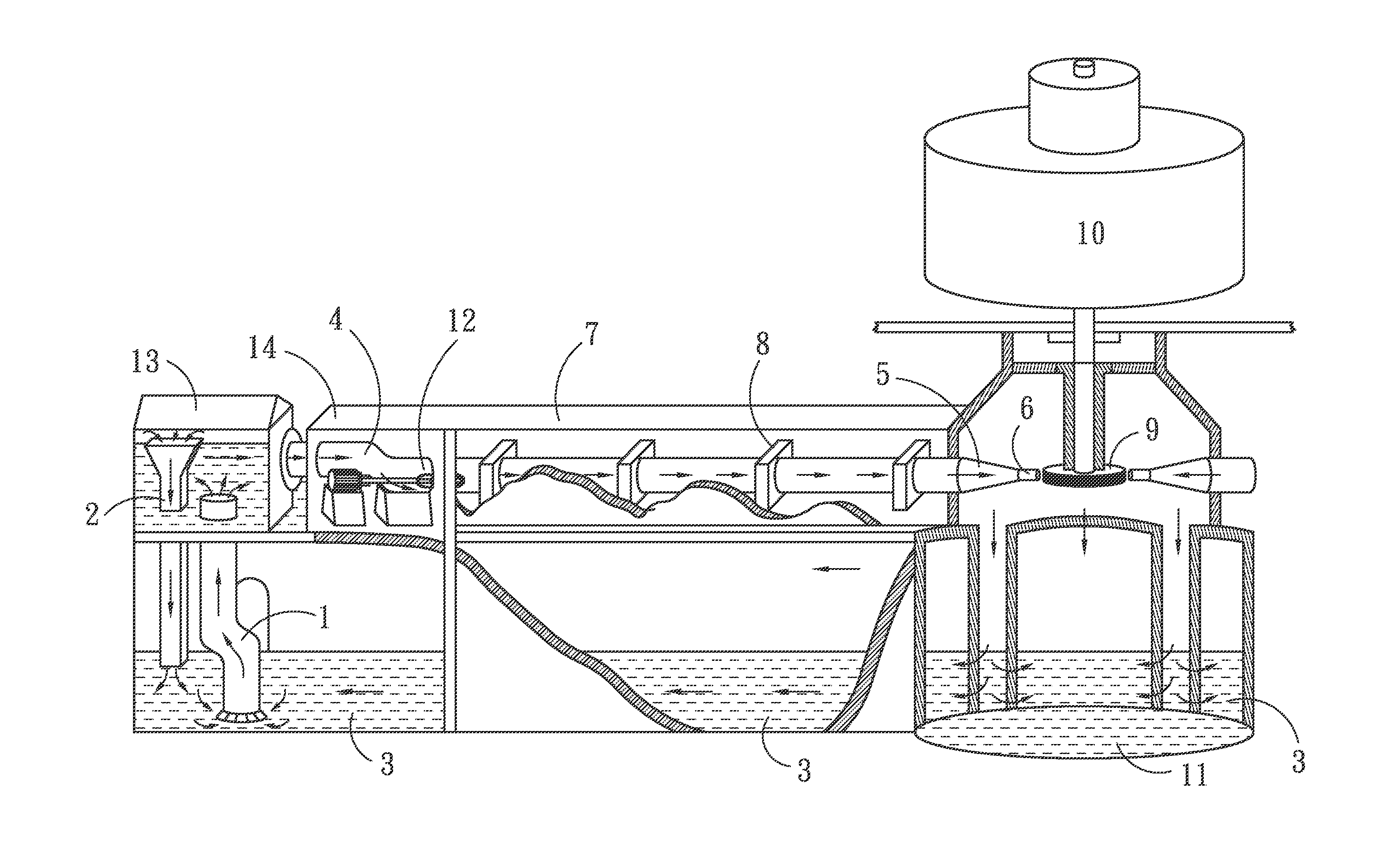
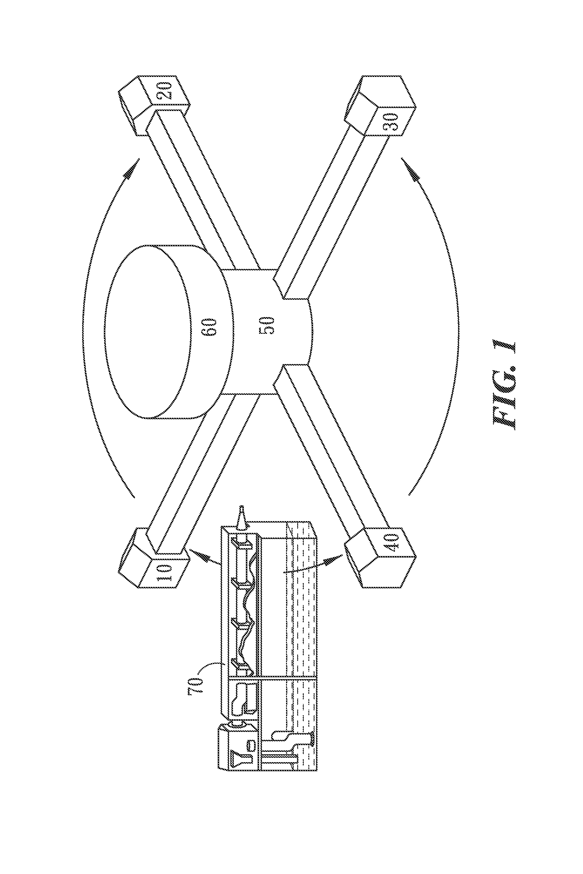
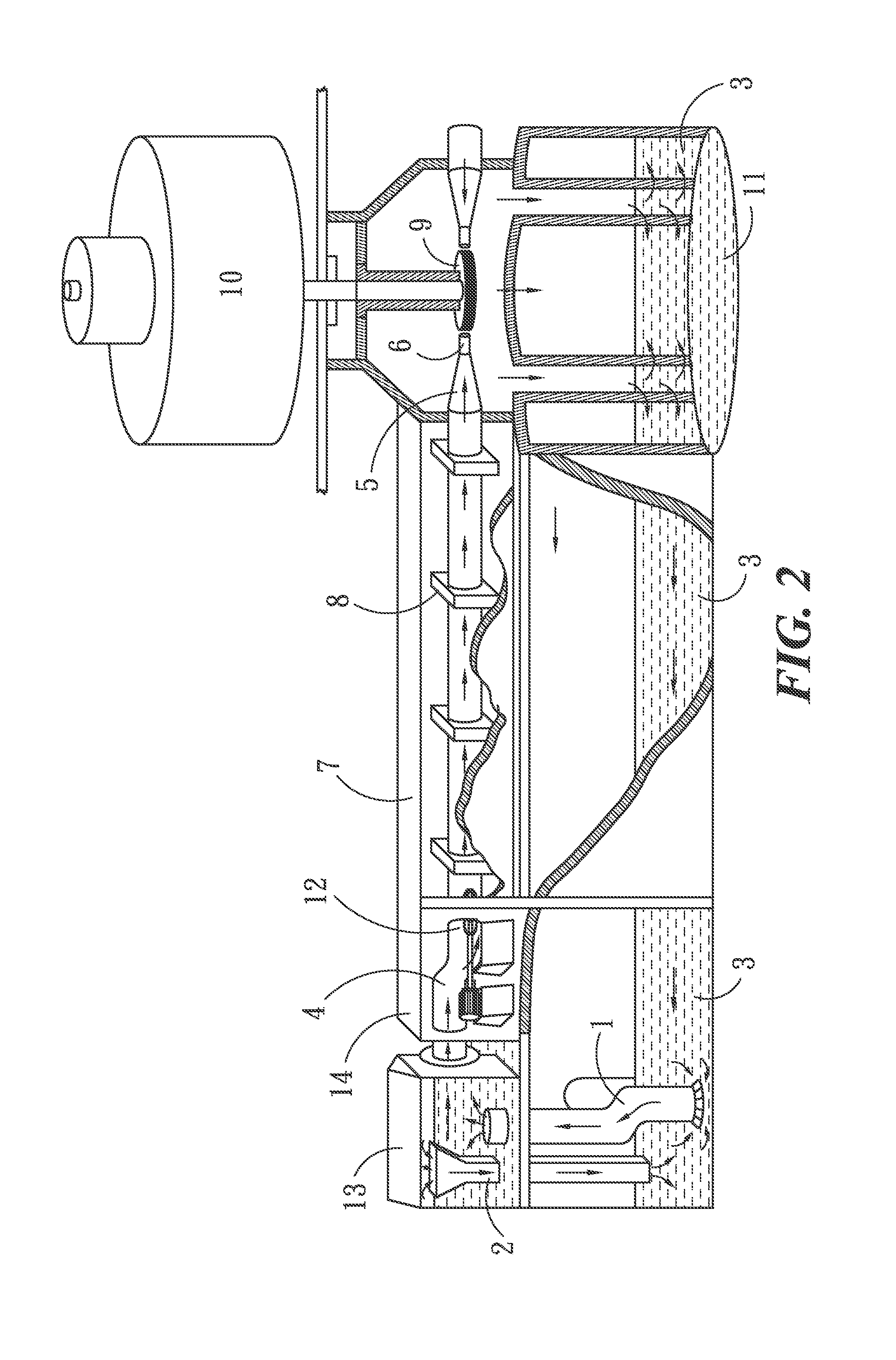
[0020]As shown in FIG. 1 through FIG. 4, the power generator system utilizing circulatory water flow in taper conduit (abridged as present system afterward) of the present invention comprises 1 to 6 nozzles and a Pelton generator unit. The nozzles of the present system will be defined as the jet components as its structure includes a tail water pumping device and three conduits a pressures pump.

[0021]For convenient to illustrate, there provides a specially designed generating equipment composed of a including four nozzles 10,20,30 and 40, an turbine chamberi 50, and a generator 60 with generation capacity of 130 MW˜180 MW. Each of the jet component 10,20,30,40 is in an elongated shape parting 90° one another and facing to the centrally situated generator 60 so as to form a large symbol of cross. The inner structure of the jet component 70 will be described later.

[0022]The structure of the power generator system utilizing the jet power of circulatory water flow in taper conduits

[0023...


PUM


Abstract

A power generator system utilizing the jet power of circulatory water flow in taper conduits is provided. The system comprises four jet components (10,20,30,40), a Pelton turbine generators and a pumping-up tail water circulation device. The jet components (10,20,30,40) comprises a taper conduits. The taper conduit is combined by a front big diameter conduit (12), a middle 30° taper conduit (5), and a rear small diameter nozzle (6). A horizontal high pressured pump (4) is provided in the front big diameter conduit (12), and supplies enough power to the water flow in the conduit when it runs. The taper conduit (5) can increase the velocity of water flow to form high speed jet flow of the rear small diameter nozzle (6). The group of Pelton turbine generators is driven to generate electricity by utilizing the jet flow. The pumping-up tail water circulation device pumps the tail water from the sealed tail water pond to the ground, to circularly supply the water needed by the taper conduit.

Description

BACKGROUND OF THE INVENTION[0001]1. Field of the invention[0002]The present invention relates to hydraulic power generation system, and in particular, to a power generator system utilizing the jet power of circulatory water flow in taper conduits.[0003]2. Description of the Prior Art[0004]Presently the energy source of the whole world essentially depends on the large amount of petroleum to maintain human regular life. The economic and cultural growth of the whole world results in producing a large amount of CO2 which brings about a severe problem of environmental contamination that leads to causing the world improper for all kinds of living creatures to maintain their health. Keeping pace with the progress of human civilization the necessity of energy is so eager that accelerates the gloval warmth to cause the world more improper for all the creatures and vigitation to survive.[0005]Another problem is that when the final day of using up petroleum energy comes true, the whole world w...

Claims


Application Information

Patent Timeline
IPC IPC(8): F03B17/02F03B1/00
CPCF03B17/02F03B1/00F03B17/005Y02E10/20
Inventor TENG, CHING-SHIH
Owner TENG CHING SHIH
Why Eureka
Try Eureka