Wireless Energy Transfer for Misaligned Resonators

a technology of misalignment and resonators, applied in the direction of transformer/inductance details, transformer/inductance circuits, inductances, etc., can solve the problems of unintentional radiation interference with other electrical systems, inefficient methods, and inefficient power transfer for reasonable distances, etc., to achieve the effect of reducing the degradation of coupling due to misalignmen

Inactive Publication Date: 2014-07-17
MITSUBISHI ELECTRIC RES LAB INC
View PDF9 Cites 64 Cited by
  • Summary
  • Abstract
  • Description
  • Claims
  • Application Information

AI Technical Summary

Benefits of technology

[0008]Embodiments of the invention are based on the realization that coupling degradation due to misali

Problems solved by technology

That method is inefficient because power decreases as the inverse square distance between the antennas, so power transfer for reasonable distances, e.g., 1 to 2 meters, is inefficient.
Additionally, since the transmitting system radiates plane waves, unintentional radiation can interfere with other e

Method used


Image

  • Wireless Energy Transfer for Misaligned Resonators
  • Wireless Energy Transfer for Misaligned Resonators
  • Wireless Energy Transfer for Misaligned Resonators

Examples


Embodiment Construction

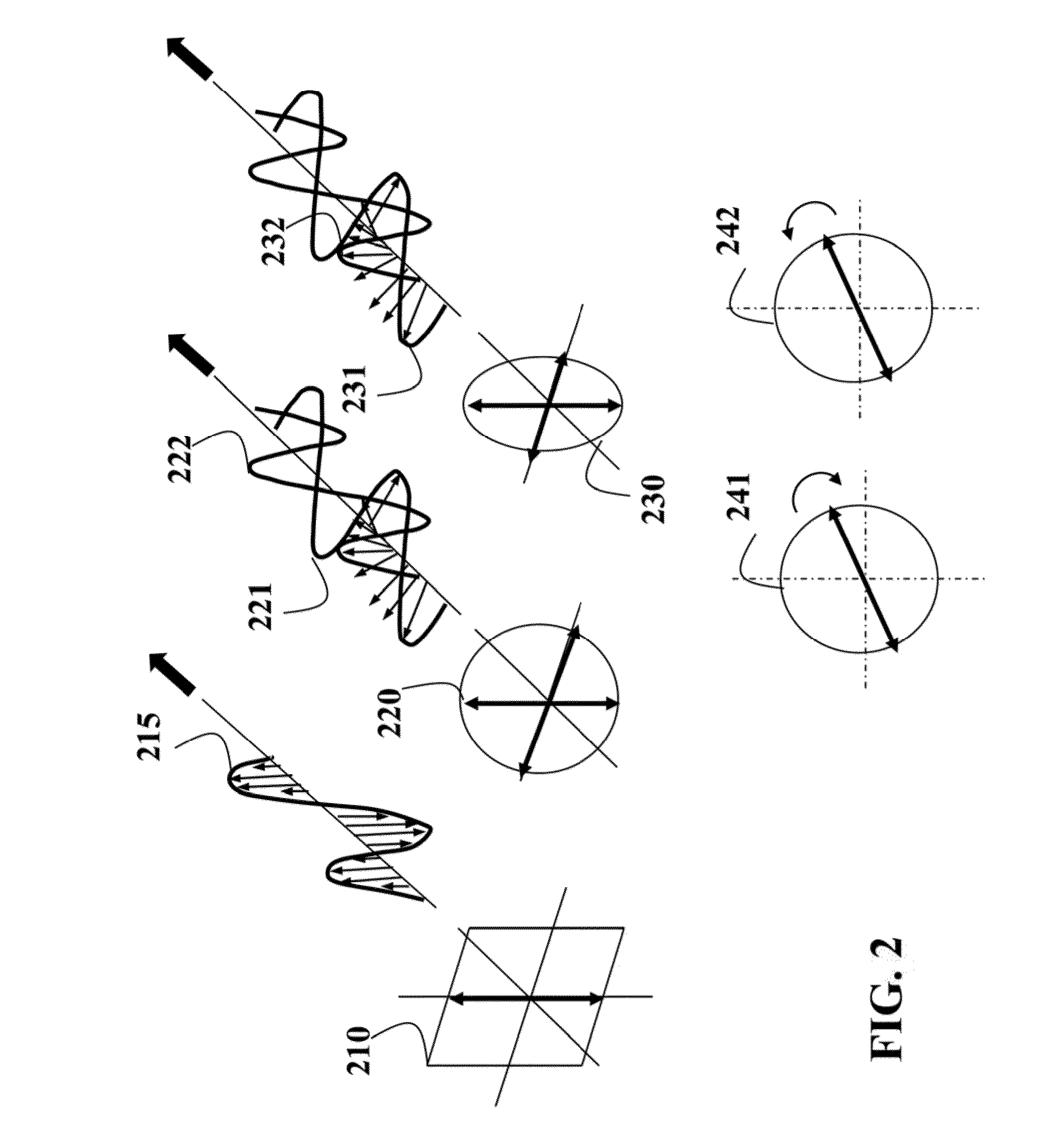
[0037]For wireless charging applications, an energy receiving device, i.e., a sink, may be mobile and not aligned well with an energy transmitting device, i.e., a source. It is desirable to improve such misalignment tolerance for more efficient energy transfer. Embodiments of the invention are based on a general realization that misalignment tolerance between the source and the sink can be improved with a circularly polarized magnetic field.

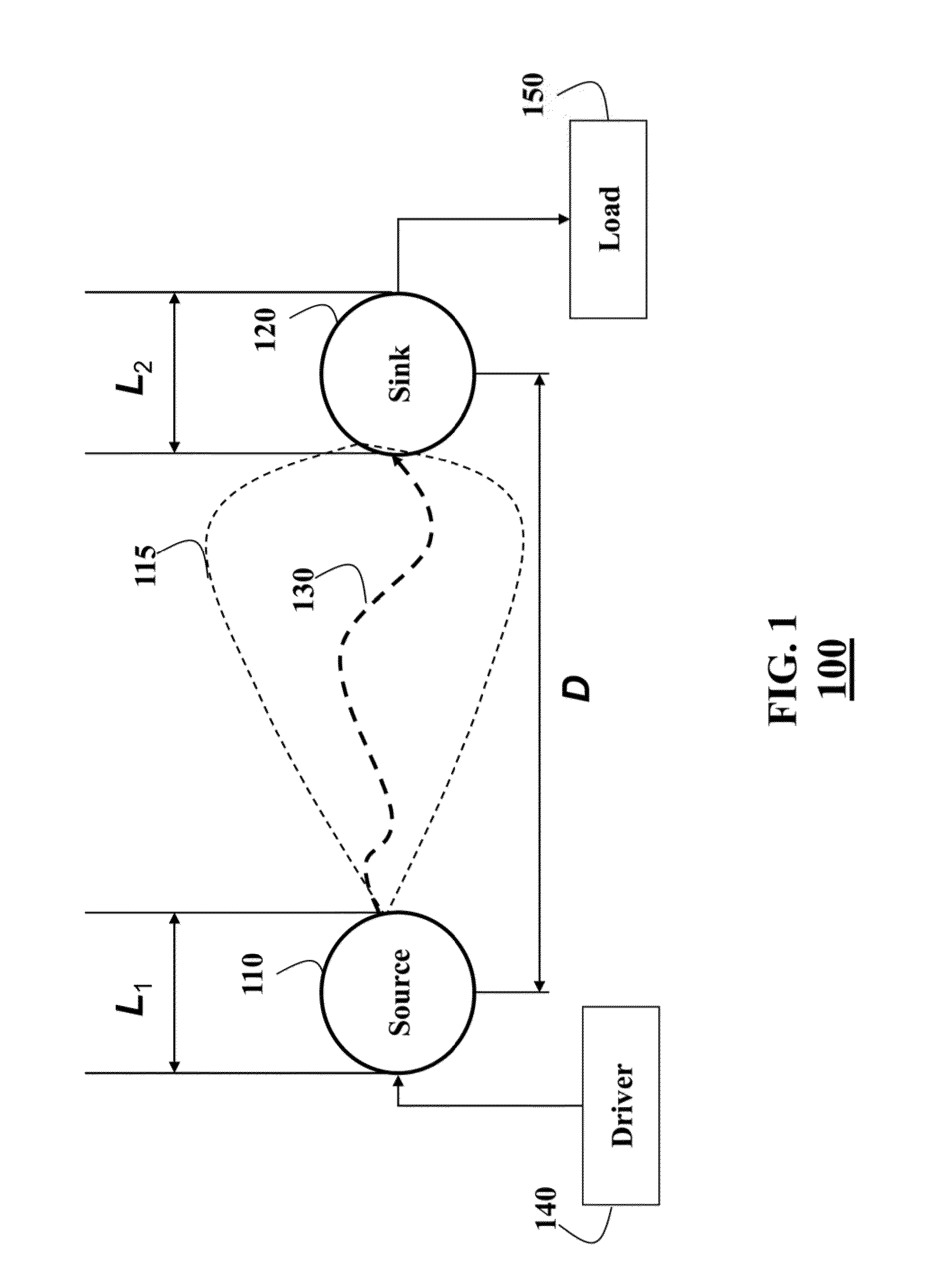
[0038]FIG. 1 shows a resonant coupling system 100 for exchanging energy between a first resonator, e.g., a source 110, and a second resonator, e.g., a sink 120, according to some embodiments of the invention. A driver 140 inputs the energy into the resonant source to form an oscillating electromagnetic field 115. In various embodiments of the invention, the field 115 is circularly polarized.

[0039]The excited electromagnetic field attenuates at a rate with respect to the excitation signal frequency at driver or self-resonant frequency of source an...


PUM


Abstract

A system for transferring energy wirelessly includes a source for generating a circular polarized field in response to receiving the energy and a sink strongly coupled to the source for receiving the energy wirelessly via a resonant coupling of the field.

Description

FIELD OF THE INVENTION [0001]The present invention relates generally to transferring energy, and more particularly, to improving wireless energy transfer between misaligned resonators.BACKGROUND OF THE INVENTION[0002]Various methods have being developed to use wireless power transmission between a transmitter and a receiver coupled to a device. Such methods generally fall into two categories. One method is based on a far-field radiation propagated between a transmit antenna and a receive antenna. The receive antenna collects the power and rectifies the power for use. That method is inefficient because power decreases as the inverse square distance between the antennas, so power transfer for reasonable distances, e.g., 1 to 2 meters, is inefficient. Additionally, since the transmitting system radiates plane waves, unintentional radiation can interfere with other electrical systems if not properly controlled by filtering.[0003]Other methods for wireless energy transmission techniques ...

Claims


Application Information

Patent Timeline
IPC IPC(8): H01F38/14
CPCH01F38/14H01F27/36H01F27/361H01F27/363H01F27/366
Inventor WANG, BINGNANWU, JINGYERAZUNIS, WILLIAMTEO, KOON HOO
Owner MITSUBISHI ELECTRIC RES LAB INC
Why Eureka
Try Eureka