Ink jet printing apparatus
a printing apparatus and jet technology, applied in printing and other directions, can solve the problems of ink leakage outside, ink in the cap, and unstable meniscus of ink at the ejection port of the nozzle,
- Summary
- Abstract
- Description
- Claims
- Application Information
AI Technical Summary
Benefits of technology
Problems solved by technology
Method used
Image

Examples
first embodiment
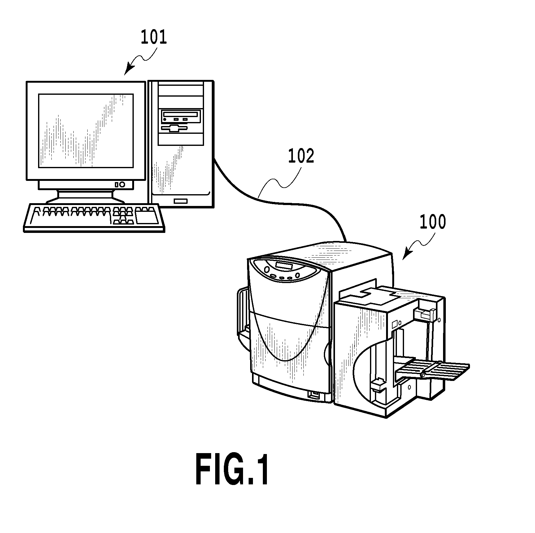
[0026]FIG. 1 is a schematic diagram illustrating a configuration of a printing system that includes an ink jet printing apparatus (hereinafter referred to simply as a printing apparatus) 100 according to the present invention.
[0027]The printing apparatus 100 of this embodiment is a full-line type that can print a color image, as will be described later, and is connected to a host computer (a host apparatus) 101 by a printer cable 102. The printing apparatus 100 receives, via the printer cable 102, various data obtained by processing performed by the host apparatus 101, and begins the printing operation.
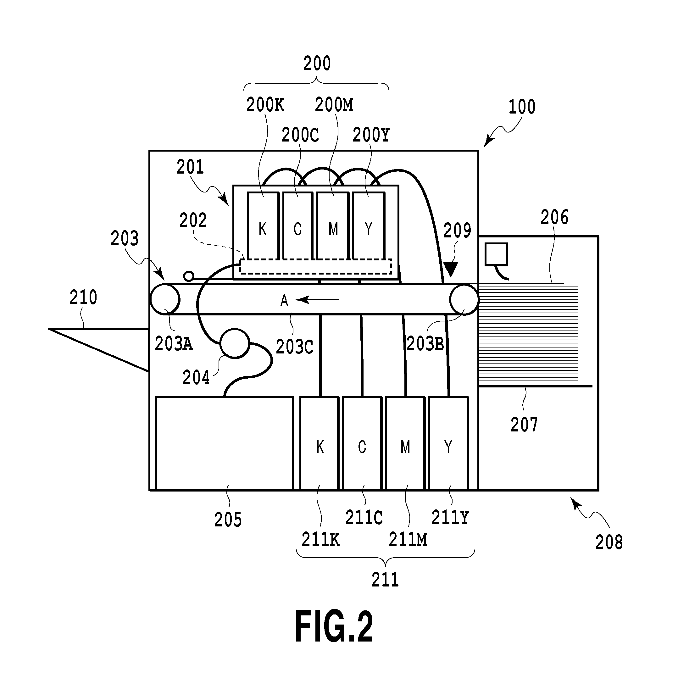
[0028]FIG. 2 is a schematic diagram illustrating an arrangement of a primary section of the printing apparatus 100.
[0029]A print head unit 201 of the printing apparatus 100 includes print heads 200 (200K, 200C, 200M and 200Y) for ejecting black, cyan, magenta and yellow inks, respectively. These print heads 200 form an elongated line head where nozzle allays are extended in a directio...
second embodiment
[0051]FIG. 8 is a flowchart for explaining the ink discharge operation for the cap unit according to a second embodiment of the present invention, and to avoid redundant explanations, the same step numbers are provided for the same processes as in FIG. 6, for the previous embodiment.
[0052]In the previous embodiment, at step S4, the CPU 301 determines the cap cleaning has been completed, and at step S5, halts the pump 204 and, thereafter, advances the processing to the next step S6. In this embodiment, however, when the processing proceeds from step S4 to step S6, the CPU 301 does not halt the pump 204. Further, when the CPU 301 ascertains, at step S8, that the cleaning time for the air release ports 402 has arrived, the CPU 301 determines whether the pump 204 is currently being driven (step S21). When the pump 204 is not being driven, at step S9 the CPU 301 begins the driving of the pump 204, and moves to step S10. When the pump 204 is currently being driven, the CPU 301 performs th...
third embodiment
[0054]In the first and second embodiments described above, the time to start the cleaning operation for the air release ports 402 is determined based on the total number of ink droplets ejected into the caps 212 for the preliminary ejection. In this embodiment, as will be described later, the temperature of the print head 200 and the environmental temperature are employed to control the cleaning operation for the air release ports 402. As a result, a more appropriate period for driving the pump 204 can be set, and the throughput is improved.
[0055]FIG. 9 is a flowchart for explaining the cap unit cleaning operation according to this embodiment. In this embodiment, the cleaning operation for all of the air release ports 402 (402K, 402C, 402M and 402Y) will be performed at the same time.
[0056]After the printing operation by the printing apparatus 100 has been completed, the CPU 301 obtains a temperature T1 of the print head 200 and an environmental temperature T2 for the printing appar...
PUM
 Abstract
Description
Claims
Application Information
 - R&D
- Intellectual Property
- Life Sciences
- Materials
- Tech Scout
- Unparalleled Data Quality
- Higher Quality Content
- 60% Fewer Hallucinations
Browse by: Latest US Patents, China's latest patents, Technical Efficacy Thesaurus, Application Domain, Technology Topic, Popular Technical Reports.
© 2025 PatSnap. All rights reserved.Legal|Privacy policy|Modern Slavery Act Transparency Statement|Sitemap|About US| Contact US: help@patsnap.com