Endoscope

Active Publication Date: 2014-07-17
OLYMPUS CORP
View PDF4 Cites 10 Cited by
  • Summary
  • Abstract
  • Description
  • Claims
  • Application Information

AI Technical Summary

Benefits of technology

[0022]The present invention affords an advantage in that an image whose depth of field i

Problems solved by technology

However, there is a problem in that the image quality is deteriorated due to an increase i

Method used


Image

  • Endoscope
  • Endoscope
  • Endoscope

Examples


Example

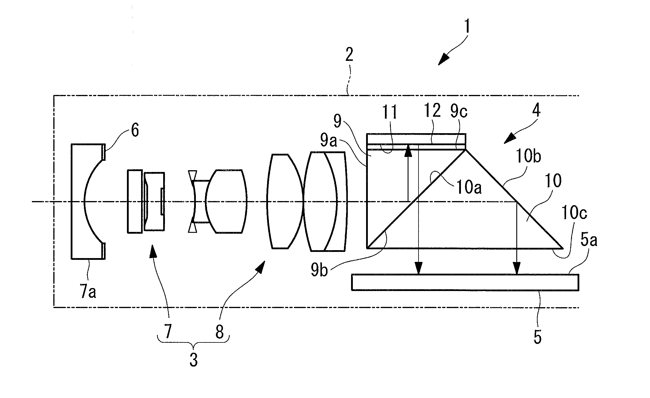
[0032]An endoscope according to an embodiment of the present invention will be described below with reference to the drawings.

[0033]As shown in FIG. 1, an endoscope 1 according to this embodiment is provided with an objective optical system 3 that is disposed in an inserted portion 2 which is inserted into an examination subject, an optical-path splitting part 4 for splitting light collected by the objective optical system 3 into two optical paths, an imaging device 5 that acquires two images at the same time by capturing the light split by the optical-path splitting part 4, and a flare diaphragm (a blocking part) 6 that partially cuts out the two optical images formed on the imaging device 5.

[0034]As shown in FIG. 1, the objective optical system 3 is provided with, sequentially from the object side, a negative lens group 7 and a positive lens group 8. Light that is coming from a wide viewing-field area and that is refracted by the negative lens group 7 is focused by the positive le...


PUM


Abstract

An endoscope includes an objective optical system at a distal end of an inserted portion to acquire a subject image; a part that splits the subject image into two optical images focused differently; an imaging device that acquires two images by simultaneously capturing the optical images arranged on an imaging surface; and a part for cutting out at least abutting portions of the optical images on the imaging device, wherein A+B>C+D, where A is half the maximum length of light-receiving regions for the optical images at the imaging surface; where TW is an entry angle at the imaging surface when A is at the maximum image height and d is an optical-path-length difference between the optical images, B=d×tanTW; C is half the length of the light-receiving regions in a direction of the optical images arranged on the imaging surface; and D is a distance between the two light-receiving regions.

Description

CROSS-REFERENCE TO RELATED APPLICATIONS[0001]This is a continuation of International Application PCT / JP2013 / 070316, with an international filing date of Jul. 26, 2013, which is hereby incorporated by reference herein in its entirety. This application claims the benefit of Japanese Patent Application No. 2012-190436, the contents of which are incorporated herein by reference.TECHNICAL FIELD[0002]The present invention relates to an endoscope.BACKGROUND ART[0003]In equipment provided with an imaging device, including endoscopes, it is generally known that increasing the number of pixels in an imaging device decreases a depth of field thereof. That is, in an imaging device, when the pixel pitch (vertical / horizontal dimension of one pixel) is decreased in order to increase the number of pixels, because the permissible circle of confusion is also decreased in association with this, the depth of field of an imaging apparatus is decreased. In order to increase the depth of field, for exampl...

Claims


Application Information

Patent Timeline
IPC IPC(8): G02B23/24H04N7/18
CPCH04N7/183G02B23/243A61B1/00096A61B1/00188A61B1/051G02B27/0075G02B27/1066A61B1/05G02B21/36G02B23/24G02B23/26
Inventor SUGA, TAKESHITSUYUKI, HIROSHIKONNO, MITSUJIRO
Owner OLYMPUS CORP
Why Eureka
Try Eureka