
Fan

a fan and fan body technology, applied in mechanical equipment, non-positive displacement pumps, liquid fuel engines, etc., can solve the problems of increasing the noise generated within the casing due to the passage of air through the casing, and achieve the effect of increasing the degree of entrainment, increasing the flow rate of combined air flow, and relatively high surface area of the outer profil

Inactive Publication Date: 2014-07-17
DYSON TECH LTD
View PDF6 Cites 12 Cited by
  • Summary
  • Abstract
  • Description
  • Claims
  • Application Information

AI Technical Summary

Benefits of technology

The invention is a fan assembly used in air conditioning units that has two separate air streams generated by separate motors and impellers. This reduces noise and allows for a smaller size of the motors and impellers. The first inlet port has a larger cross-sectional area than the second inlet port to minimize turbulence in the outlet section. The outlet section has the same cross-sectional area as the second inlet port. The technical effects of this invention are reduced noise, compact size, and minimized turbulence in the air conditioning unit.

Problems solved by technology

The noise generated within the casing due to the passage of air through the casing tends to increase with increasing air stream velocity.

Method used


Image

  • Fan
  • Fan
  • Fan

Examples


Embodiment Construction

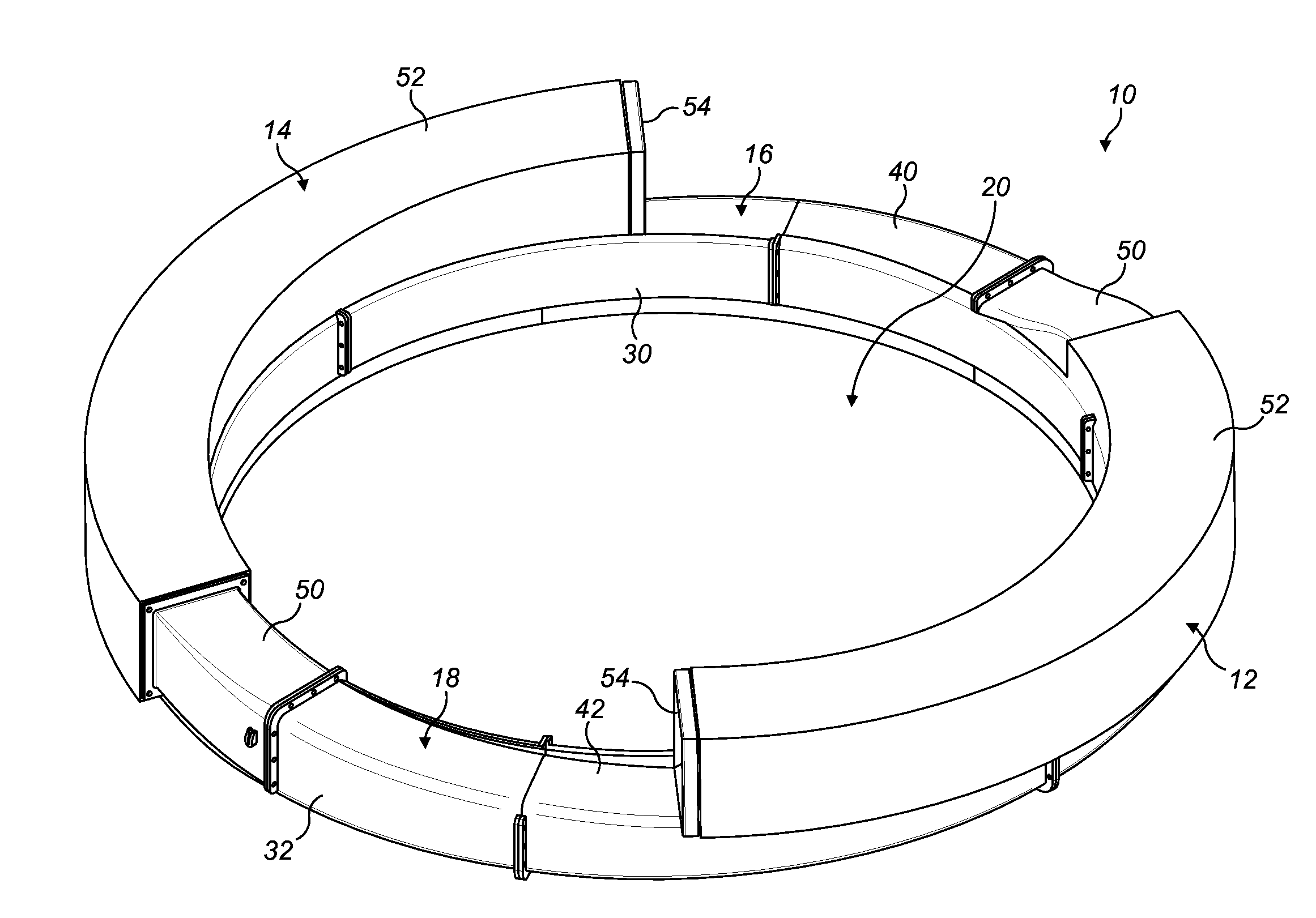
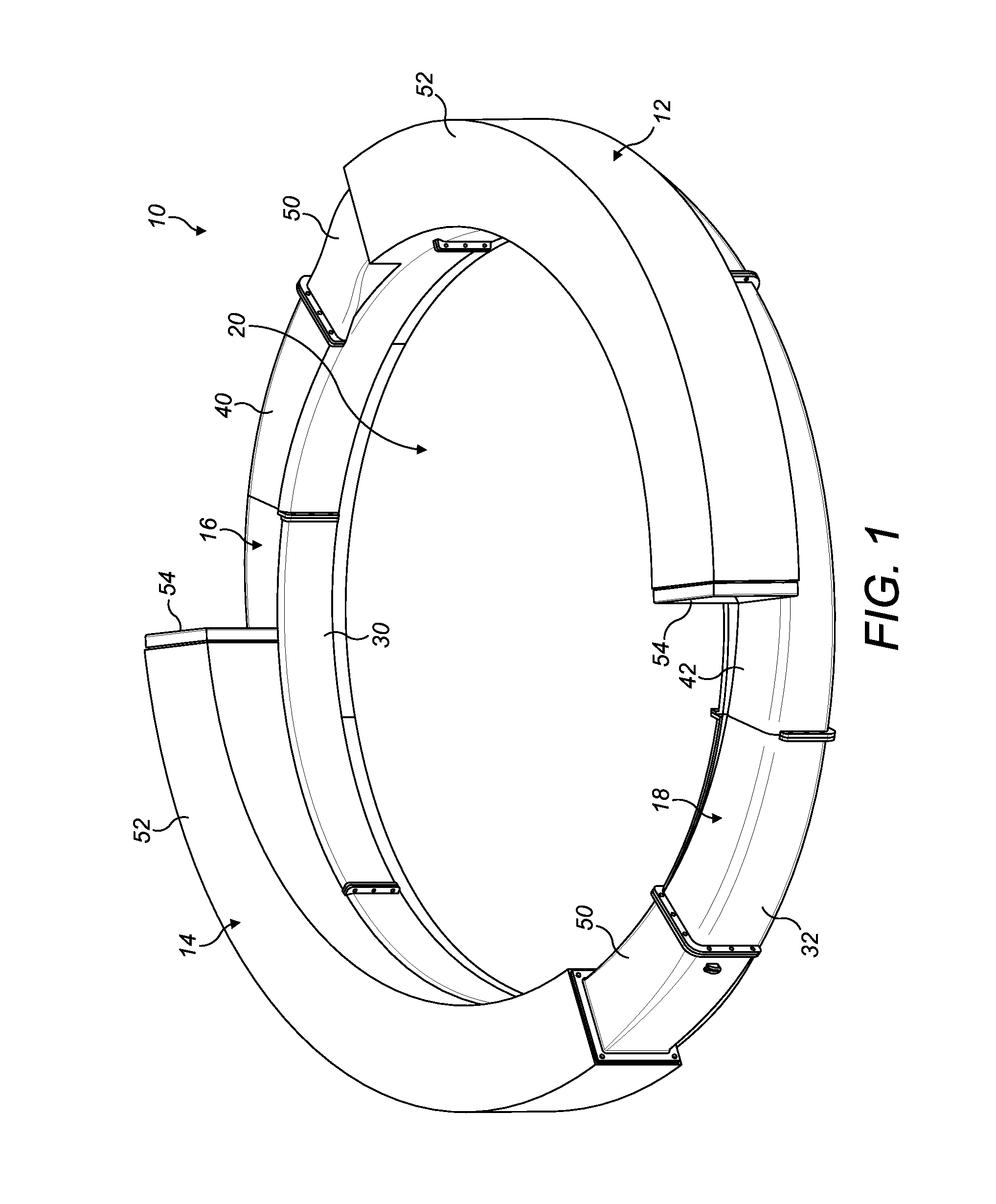
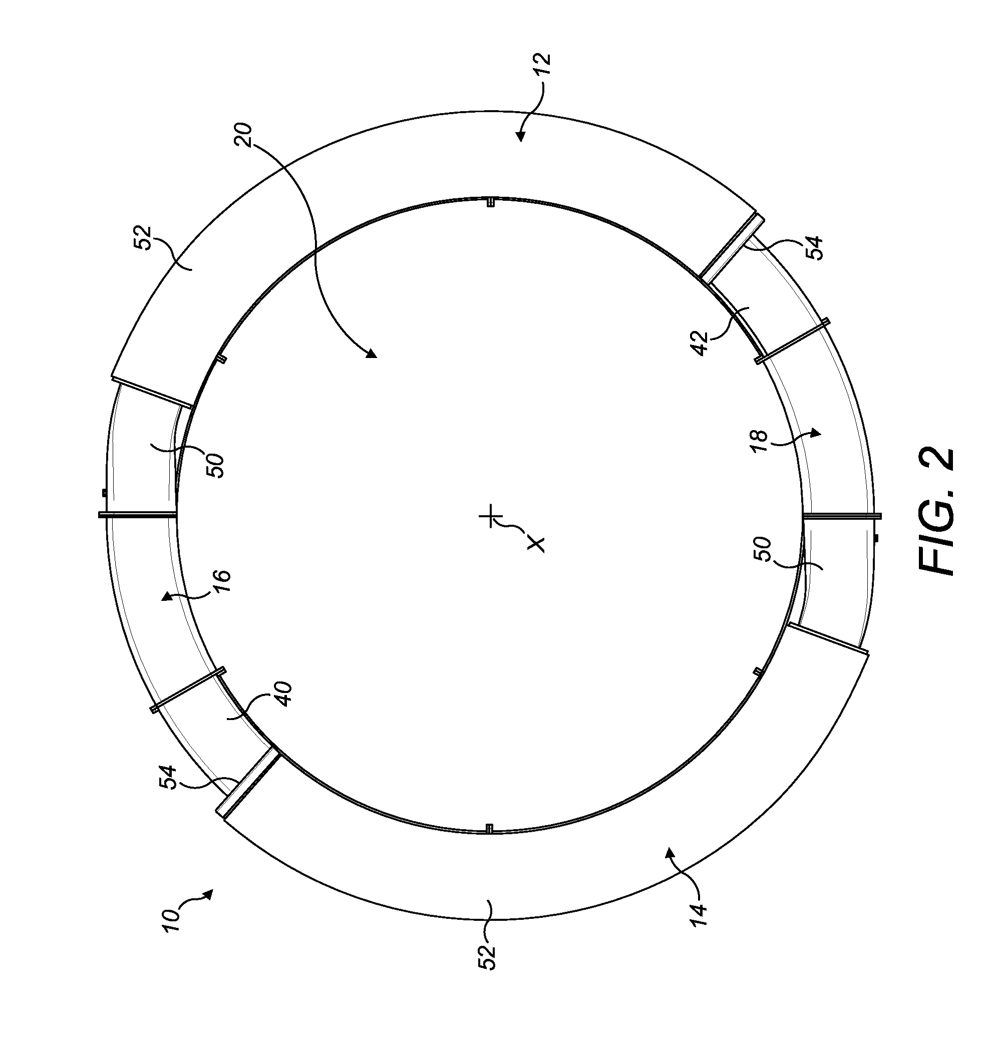
[0031]FIGS. 1 to 4 are external views of an example of a fan assembly 10 for generating an air flow within a room. In this example, the fan assembly 10 forms part of a ceiling fan which is connectable to a ceiling of a room. A support assembly (not shown) is provided for supporting the fan assembly 10 on the ceiling of the room. The support assembly may comprise any form of known support or supports, such as a frame, arms, chains, or the like, for supporting the fan assembly 10 on the ceiling.

[0032]The fan assembly 10 comprises an annular casing. The casing has a first inlet section 12 and a second inlet section 14 for drawing a primary air flow into the fan assembly 10. The casing also has a first outlet section 16 for receiving air from the first inlet section 12, and a second outlet section 18 for receiving air from the second inlet section 14. The outlet sections 16, 18 are semi-circular in shape, and are connected together so as to extend about a central bore axis X to define a...


PUM


Abstract

A fan assembly for generating an air flow within a room includes a casing having a plurality of inlet sections and an outlet section for receiving air from the inlet sections. Each inlet section has an air inlet, an impeller and a motor for driving the impeller to draw an air flow through the air inlet section and into the air outlet section. The outlet section has an interior passage for receiving air from the inlet sections and an air outlet. The casing defines a bore about which the interior passage extends and through which a secondary air flow from outside the fan assembly is drawn by the air emitted the air outlet.

Description

REFERENCE TO RELATED APPLICATIONS[0001]This application claims the priority of United Kingdom Application No. 1300629.1, filed Jan. 14, 2013, the entire contents of which are incorporated herein by reference.FIELD OF THE INVENTION[0002]The present invention relates to a fan assembly for generating an air flow within a room. In its preferred embodiment, the present invention relates to a ceiling fan.BACKGROUND OF THE INVENTION[0003]A number of ceiling fans are known. A standard ceiling fan comprises a set of blades mounted about a first axis and a drive also mounted about the first axis for rotating the set of blades.SUMMARY OF THE INVENTION[0004]In a first aspect, the present invention provides a fan assembly for generating an air flow within a room, the fan assembly comprising a casing having a plurality of inlet sections and a plurality of outlet sections each for receiving air from a respective inlet section, each inlet section comprising an air inlet, an impeller and a motor for...

Claims


Application Information

Patent Timeline
Patent Type & Authority Applications(United States)
IPC IPC(8): F04D29/40F04F5/16
CPCF04F5/16F04D29/403F04D25/08F04D25/16F04D25/088F04D29/441
Inventor NICOLAS, FREDERICKOWALCZYK, LUKASZ ANDRZEJSTEWART, NEIL ANDREW
Owner DYSON TECH LTD
Learn More